
Owner Manual

1A-11
RL5000
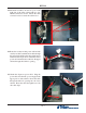
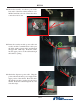
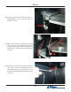
11. Mount the assembly onto the two posts on the
back wall of the inner cabinet with two 1/4-
20 Hex Jam Nuts as shown. Ensure the cable
connections face down.
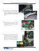
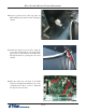
12. Route the security module power cable and
security module communications cable past
the back opening (green circle) and through
the upper left cable clips. Route the cables
into the upper portion of the cabinet through
the left hole opening.
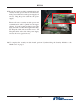
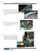
13. Obtain the dispenser power cable. Plug the
power cable into the unit’s power supply in the
upper portion of the cabinet. Route the cable
through the left hole opening into the lower
cabinet. Route the cable through the two left
side cable clips.