EJ TO SECURITY MODULE UPGRADE RL5000 FT5000 XSCALE AND X2 TDN 07103-00224 December 12, 2013 Corporate Headquarters 21405 B Street Long Beach, MS 39560 Phone: (800) 259-6672 Fax: (228) 868-9445 COPYRIGHT NOTICE © 2013 Triton. All Rights Reserved.
EJ TO SECURITY MODULE UPGRADE PROCEDURES Document Updates October 21, 2011 December 2, 2011 December 12, 2013 Original Edits to cover page to indicated RL/FT 5K Xscale and X2 only, not XP. Seperated RL5xxx by cabinet serial number and added new cable routing.
INTRODUCTION TABLE OF CONTENTS INTRODUCTION & NOTES............................................................................................................................. 4 SECTION 1A..........RL5000 SDD..................KIT NUMBER 06200-00187 ..............................................1A-1 SECTION 1B..........RL5000 NMD50.............KIT NUMBER 06200-00186 ..............................................1B-1 SECTION 2............FT5000............................KIT NUMBER 06200-00174 .............
EJ TO SECURITY MODULE UPGRADE PROCEDURES INTRODUCTION PURPOSE This guide covers the steps for replacing your current Electronic Journal (EJ) with a new Security Module (SM). The new module adds additional security to the mainboard to dispenser communications path, and increases the size of the journal file. These procedures include a list of all tools and hardware necessary for the replacement as well as the steps involved.
SECTION 1A ELECTRONIC JOURNAL TO SECURITY MODULE UPGRADE RL5000 CABINET OR VAULT SDD 07103-00224 DECEMBER 12, 2013
EJ TO SECURITY MODULE UPGRADE PROCEDURES REQUIRED PARTS AND TOOLS TOOLS REQUIRED KIT 06200-00187 Part # 09105-80309 09120-00900 09120-00167 09120-07017 03011-01918 03072-00038 02301-00024 02301-00027 02054-00169 02302-00032 03072-00008 03072-00015 #2 Phillips screwdriver with a 4 inch shank 11/32” & 7/16” hollow shaft nut drivers Side cut pliers USB flash drive Small paperclip (straightened out) RL5000 Cabinet / Vault with SDD - EJ to SM Conversion Kit Description FT/RL/Traverse Live- (PPA) Security Mo
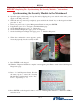
RL5000 Skip to page 5 and perform the security module installation and cable routing BEFORE completing the “Synchronizing the Security Module...” instructions. Synchronizing the Security Module to the Mainboard 1. Open the upper cabinet and power up the unit by flipping the power switch on the unit’s power supply to the ON position (I). 2. When the unit is powered up completely, press and hold the “blank” key on the keypad and then press the “1” key. 3.
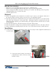
EJ TO SECURITY MODULE UPGRADE PROCEDURES RL5000 UPGRADE BEFORE PROCEEDING: • • • • Ensure all of your Journal Records have been saved to a USB flash drive. Perform a proper management function shut down to remove power from the ATM. Unlock and open the ATM control panel. Turn the power switch to the OFF (0) position. If possible, unplug the ATM power cord at the wall outlet. Open the dispenser area. Removal 1. Refer to the applicable service manual for your unit for steps to remove your dispenser.
RL5000 Use the table of contents below to locate your unit’s serial number and page number of the correct installation and cable routing.
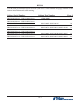
EJ TO SECURITY MODULE UPGRADE PROCEDURES Cabinet # 09700-00000 with an SDD Dispenser Right Side Mounting 8. Obtain the Security Module Flat Bracket. Insert the two posts on the bracket into the two notches on the security module. Gently push the security module towards the two posts, flexing the plastic ends slightly on both sides, to insert the single post on the bracket into the single notch on the module. Ensure the security module is sitting flush against the flat bracket. 9.
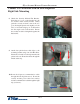
RL5000 11. Mount the assembly onto the two posts on the right side of the inner cabinet with two 1/420 Hex Jam Nut as shown. Ensure the cable connections face towards the cabinet door. 12. Route the security module power cable and the security module communication cable through the upper back middle cable clip and the upper left front cable clip as shown. Route the excess power and communication cable into the upper cabinet through the left hole opening. 13. Obtain the dispenser power cable.
EJ TO SECURITY MODULE UPGRADE PROCEDURES 14. Loop the SDD dispenser communication cable back on itself twice to condense the length of the cable to match the length of the dispenser power cable. TY Wrap the two cables together in two spots as shown. Cut off the excess TY Wraps. 15. Plug the cables into the back of the SDD dispenser and tighten the thumbscrews on the communication cable to secure it. Reinstall the dispenser into the unit. 16.
RL5000 17. Route the security module communication and security module power cable around the unit’s main power cable and over the power supply (red arrows). Plug the power cable into the power supply. Ensure all excess security module power and communication cable is pulled into the upper cabinet. Loop the security module power cable back on itself to condense the length of the cable. TY Wrap the cable and cut off the excess.
EJ TO SECURITY MODULE UPGRADE PROCEDURES Cabinet # 03015-00052 & 03015-00167 with an SDD Dispenser Back Wall Mounting 8. Obtain the Security Module Flat Bracket. Insert the two posts on the bracket into the two notches on the security module. Gently push the security module towards the two posts, flexing the plastic ends slightly on both sides, to insert the single post on the bracket into the single notch on the module. Ensure the security module is sitting flush against the flat bracket. 9.
RL5000 11. Mount the assembly onto the two posts on the back wall of the inner cabinet with two 1/420 Hex Jam Nuts as shown. Ensure the cable connections face down. 12. Route the security module power cable and security module communications cable past the back opening (green circle) and through the upper left cable clips. Route the cables into the upper portion of the cabinet through the left hole opening. 13. Obtain the dispenser power cable.
EJ TO SECURITY MODULE UPGRADE PROCEDURES 14. Loop the SDD dispenser communication cable back on itself twice to condense the length of the cable to match the length of the dispenser power cable. TY Wrap the two cables together in two spots as shown. Cut off the excess TY Wraps. 15. Plug the cables into the back of the SDD dispenser and tighten the thumbscrews on the communication cable to secure it. Reinstall the dispenser into the unit. 16.
RL5000 17. Route the security module communication and security module power cable around the unit’s main power cable and over the power supply (red arrows). Plug the power cable into the power supply. Ensure all excess security module power and communication cable is pulled into the upper cabinet. Loop the security module power cable back on itself to condense the length of the cable. TY Wrap the cable and cut off the excess.
EJ TO SECURITY MODULE UPGRADE PROCEDURES Cabinet # 03015-00793 / 03015-00833 / 03015-01340 with an SDD Dispenser Left Side Mounting 8. Insert the two posts on the cabinet wall into the two notches on the bottom of the security module as shown. 9. Gently push the security module down flexing the plastic ends slightly. Insert the single post on the cabinet wall into the notch on the top of the security module as shown. Ensure the security module is sitting flush against the cabinet wall. 10.
RL5000 11. Install a quick release cable clip with one 02054-00169 screw to the left dispenser bracket as shown. 12. Route the dispenser communication cable down in front of the dispenser tray, through the quick release cable clip and under the tray. Pull all excess cable up from behind the tray as shown. 13. Route the security module power cable and the security module communication cable through the quick release cable clip and into the upper cabinet through the back left opening as shown.
EJ TO SECURITY MODULE UPGRADE PROCEDURES 14. Install a quick release cable clip with one 02054-00169 screw in the rear left of the upper cabinet. 15. Obtain the dispenser power cable. Plug the power cable into the unit’s power supply in the upper portion of the cabinet. Route the cable through the left hole opening into the lower cabinet. 16. Plug the cables into the back of the SDD dispenser and tighten the thumbscrews on the communication cable to secure it. Reinstall the dispenser into the unit.
RL5000 17. Route all the cables in the upper cabinet through the cable clip previously installed. Route the cables under the bracket as shown. 18. In the upper cabinet, route the security module communication cable up through all four previously loosened wire plate cable clips and plug the cable into the docking/mainboard in the “dispenser” jack. Tighten the wire plate cable clips to secure the control panel cables. 19.
EJ TO SECURITY MODULE UPGRADE PROCEDURES Vault # 03015-00064 / 03015-00200 / 03015-00227 with an SDD Dispenser Back Wall Mounting 8. Obtain the Security Module Flat Bracket. Insert the two posts on the bracket into the two notches on the security module. Gently push the security module towards the two posts, flexing the plastic ends slightly on both sides, to insert the single post on the bracket into the single notch on the module. Ensure the security module is sitting flush against the flat bracket. 9.
RL5000 11. Mount the assembly onto the two posts on the back wall of the inner vault with two 1/4-20 Hex Jam Nuts as shown. Ensure the cable connections face down. 12. From the upper portion of the cabinet, remove the two bolts & washers securing the antiphishing bracket. Set aside for reinstallation. 13. Route the security module power cable and security module communications cable through the upper middle back two clips.
EJ TO SECURITY MODULE UPGRADE PROCEDURES 14. Obtain the dispenser power cable. Plug the power cable into the unit’s power supply in the upper portion of the cabinet. Route the cable through the anti-fishing bracket and the left hole opening into the vault. Route the dispenser power cable through the rear left cable clip as shown. Reinstall the two washers and two bolts to secure the anti-fishing bracket. 15.
RL5000 17. In the upper cabinet, route the security module communication cable up through all four previously loosened wire plate cable clips and plug the cable into the docking/mainboard in the “dispenser” jack. Tighten the wire plate cable clips to secure the control panel cables. 18. Route the security module communication and security module power cable around the unit’s main power cable and over the power supply (red arrows). Plug the power cable into the power supply.
EJ TO SECURITY MODULE UPGRADE PROCEDURES Vault # 03015-00798 / 03015-00212 / 03015-00841 with an SDD Dispenser Left Wall Mounting 8. Insert the two posts on the cabinet wall into the two notches on the bottom of the security module as shown. 9. Gently push the security module down flexing the plastic ends slightly. Insert the single post on the cabinet wall into the notch on the top of the security module as shown. Ensure the security module is sitting flush against the cabinet wall. 10.
RL5000 11. Install a quick release cable clip with one 02054-00169 screw to the left dispenser bracket as shown. Route the dispenser communication cable down in front of the dispenser tray, through the quick release cable clip and under the tray. Pull all excess cable up from behind the tray as shown. 12.
EJ TO SECURITY MODULE UPGRADE PROCEDURES 13. Obtain the dispenser power cable. Plug the power cable into the unit’s power supply in the upper portion of the cabinet. Route the cable through the left hole opening into the lower cabinet. 14. Plug the cables into the back of the SDD dispenser and tighten the thumbscrews on the communication cable to secure it. Reinstall the dispenser into the unit. 15.
RL5000 16. In the upper cabinet, route the security module communication and security module power cable around the unit’s main power cable and over the power supply. Plug the power cable into the power supply. Route the security module cable up through all four previously loosened wire plate cable clips and plug the cable into the docking/mainboard in the “dispenser” jack. Tighten the wire plate cable clips to secure the control panel cables. 17.
SECTION 1B ELECTRONIC JOURNAL TO SECURITY MODULE UPGRADE RL5000 CABINET OR VAULT NMD50 07103-00224 DECEMBER 12, 2013
EJ TO SECURITY MODULE UPGRADE PROCEDURES REQUIRED PARTS AND TOOLS TOOLS REQUIRED KIT 06200-00186 Part # 09105-80309 09120-00167 09120-00900 09120-07200 09120-07199 03011-01918 03072-00038 02301-00024 02301-00027 02054-00169 02302-00032 03072-00015 03072-00009 #2 Phillips screwdriver with a 4 inch shank 11/32” & 7-16” hollow shaft nut drivers Side cut pliers USB flash drive Small paperclip (straightened out) RL5000 Cabinet/Vault with NMD50 - EJ to SM Conversion Kit Description FT/RL/Traverse Live- (PPA)
RL5000 Skip to page 5 and perform the security module installation and cable routing BEFORE completing the “Synchronizing the Security Module...” instructions. Synchronizing the Security Module to the Mainboard 1. Open the upper cabinet and power up the unit by flipping the power switch on the unit’s power supply to the ON position (I). 2. Press and hold the “blank” key on the keypad and then press the “1” key. 3. Enter your password to log into Management Functions and press ENTER. 4.
EJ TO SECURITY MODULE UPGRADE PROCEDURES RL5000 UPGRADE BEFORE PROCEEDING: • • • • Ensure all of your Journal Records have been saved to a USB flash drive. Perform a proper management function shut down to remove power from the ATM. Unlock and open the ATM control panel. Turn the power switch to the OFF (0) position. If possible, unplug the ATM power cord at the wall outlet. Open the dispenser area. Removal 1. Refer to the applicable service manual for your unit for steps to remove your dispenser.
RL5000 Use the table of contents below to locate your unit’s serial number and page number of the correct installation and cable routing.
EJ TO SECURITY MODULE UPGRADE PROCEDURES Cabinet # 09700-00000 with an NMD 50 Dispenser Right Side Mounting 8. Obtain the Security Module Flat Bracket. Insert the two posts on the bracket into the two notches on the security module. Gently push the security module towards the two posts, flexing the plastic ends slightly on both sides, to insert the single post on the bracket into the single notch on the module. Ensure the security module is sitting flush against the flat bracket. 9.
RL5000 11. Mount the assembly onto the two posts on the right side of the inner cabinet with two 1/420 Hex Jam Nuts as shown. Ensure the cable connections face towards the cabinet door. 12. Route the security module power cable and the security module communication cable through the upper back middle cable clip and the upper left front cable clip as shown. Route the excess power and communication cable into the upper cabinet through the left hole opening. 13. Obtain the dispenser power cable.
EJ TO SECURITY MODULE UPGRADE PROCEDURES 14. With the dispenser still removed from the unit, peel the paper backing off one Panduit Adhesive Cable Clip and adhere it to the back right side of the NMD50 dispenser. Peel the paper backing off another Panduit Adhesive Cable Clip and adhere it to the front right side of the NMD50 dispenser. Note the orientation of the clips in the pictures. 15.
RL5000 17. Route the ground wire around to the front of the dispenser. Plug the ground wire onto the quick connect as shown. 18. Plug the Dispenser Power Cable into the side of the NMD50 as shown. 19. Tuck the ground wire under the clip on the side of the dispenser. Route the power cable through the two cable clips along the left side of the dispenser. Route the cable around to the rear of the dispenser and through the cable clip on the back left side of the NMD50.
EJ TO SECURITY MODULE UPGRADE PROCEDURES 20. Route the Dispenser data cable from the security module assembly through the two cable clips on the right side of the NMD50 dispenser as shown. (Dispenser removed from the unit for clarification) 21. Route the Dispenser data cable across the top of the dispenser, through the cable clip on the left side of the dispenser and plug it into the dispenser as shown.
RL5000 23. Route the security module communication and security module power cable around the unit’s main power cable and over the power supply (red arrows). Plug the power cable into the power supply. Ensure all excess security module power and communication cable is pulled into the upper cabinet. Loop the security module power cable back on itself to condense the length of the cable. TY Wrap the cable and cut off the excess.
EJ TO SECURITY MODULE UPGRADE PROCEDURES Cabinet # 03015-00052 & 03015-00167 with an NMD 50 Dispenser Back Wall Mounting 8. Obtain the Security Module Flat Bracket. Insert the two posts on the bracket into the two notches on the security module. Gently push the security module towards the two posts, flexing the plastic ends slightly on both sides, to insert the single post on the bracket into the single notch on the module. Ensure the security module is sitting flush against the flat bracket. 9.
RL5000 12. Mount the assembly onto the two posts on the back wall of the inner cabinet with two 1/420 Hex Jam Nuts as shown. Ensure the cable connections face down. 13. Route the security module power cable and security module communications cable past the back opening (green circle) and through the upper left cable clips. Route the cables into the upper portion of the cabinet through the left hole opening. 14. Obtain the dispenser power cable.
EJ TO SECURITY MODULE UPGRADE PROCEDURES 15. With the dispenser still removed from the unit, peel the paper backing off one Panduit Adhesive Cable Clip and adhere it to the back right side of the NMD50 dispenser. Peel the paper backing off another Panduit Adhesive Cable Clip and adhere it to the front right side of the NMD50 dispenser. Note the orientation of the clips in the pictures. 16.
RL5000 18. Route the ground wire around to the front of the dispenser. Plug the ground wire onto the quick connect as shown. 19. Plug the Dispenser Power Cable into the side of the NMD50 as shown. 20. Tuck the ground wire under the clip on the side of the dispenser. Route the power cable through the two cable clips along the left side of the dispenser. Route the cable around to the rear of the dispenser and through the cable clip on the back left side of the NMD50.
EJ TO SECURITY MODULE UPGRADE PROCEDURES 21. Route the Dispenser data cable from the security module assembly through the two cable clips on the right side of the NMD50 dispenser as shown. (Dispenser removed from the unit for clarification) 22. Route the Dispenser Communication Cable across the top of the dispenser, through the cable clip on the left side of the dispenser and plug it into the dispenser as shown.
RL5000 23. Route the security module communication and security module power cable around the unit’s main power cable and over the power supply (red arrows). Plug the power cable into the power supply. Ensure all excess security module power and communication cable is pulled into the upper cabinet. Loop the security module power cable back on itself to condense the length of the cable. TY Wrap the cable and cut off the excess.
EJ TO SECURITY MODULE UPGRADE PROCEDURES Cabinet # 03015-00793 / 03015-00833 / 03015-01340 with an NMD 50 Dispenser Left Side Mounting 8. Insert the two posts on the cabinet wall into the two notches on the bottom of the security module as shown. 9. Gently push the security module down flexing the plastic ends slightly. Insert the single post on the cabinet wall into the notch on the top of the security module as shown. Ensure the security module is sitting flush against the cabinet wall. 10.
RL5000 11. Route the security module power cable and the security module communication cable through the quick release cable clip and into the upper cabinet through the back left opening as shown. 12. Install a quick release cable clip with one 02054-00169 screw in the rear left of the upper cabinet. 13. Obtain the dispenser power cable. Plug the power cable into the unit’s power supply in the upper portion of the cabinet. Route the cable through the left hole opening into the lower cabinet.
EJ TO SECURITY MODULE UPGRADE PROCEDURES 14. With the dispenser still removed from the unit, peel the paper backing off one Panduit Adhesive Cable Clip and adhere it to the back right side of the NMD50 dispenser. Peel the paper backing off another Panduit Adhesive Cable Clip and adhere it to the front right side of the NMD50 dispenser. Note the orientation of the clips in the pictures. 15.
RL5000 17. Route the ground wire around to the front of the dispenser. Plug the ground wire onto the quick connect as shown. 18. Plug the Dispenser Power Cable into the side of the NMD50 as shown. 19. Tuck the ground wire under the clip on the side of the dispenser. Route the power cable through the two cable clips along the left side of the dispenser. Route the cable around to the rear of the dispenser and through the cable clip on the back left side of the NMD50.
EJ TO SECURITY MODULE UPGRADE PROCEDURES 20. Route the Dispenser data cable from the security module assembly through the two cable clips on the right side of the NMD50 dispenser as shown. (Dispenser removed from the unit for clarification) 21. Route the Dispenser Communication Cable across the top of the dispenser, through the cable clip on the left side of the dispenser and plug it into the dispenser as shown.
RL5000 23. In the upper cabinet, route the security module communication cable up through all four previously loosened wire plate cable clips and plug the cable into the docking/mainboard in the “dispenser” jack. Tighten the wire plate cable clips to secure the control panel cables. 24. Route the security module communication and security module power cable around the unit’s main power cable and over the power supply (red arrows). Plug the power cable into the power supply.
EJ TO SECURITY MODULE UPGRADE PROCEDURES Vault # 03015-00064 / 03015-00200 / 03015-00227 with an NMD 50 Dispenser Back Wall Mounting 8. Obtain the Security Module Flat Bracket. Insert the two posts on the bracket into the two notches on the security module. Gently push the security module towards the two posts, flexing the plastic ends slightly on both sides, to insert the single post on the bracket into the single notch on the module. Ensure the security module is sitting flush against the flat bracket.
RL5000 11. Mount the assembly onto the two posts on the back wall of the inner vault with two 1/4-20 Hex Jam Nuts as shown. Ensure the cable connections face down. 12. From the upper portion of the cabinet, remove the two bolts & two washers that secure the anti-phishing bracket. Set aside for reinstallation. 13. Route the security module power cable and security module communications cable through the rear upper middle cable clip on the top of the vault.
EJ TO SECURITY MODULE UPGRADE PROCEDURES 14. Obtain the dispenser power cable. Plug the power cable into the unit’s power supply in the upper portion of the cabinet. Route the cable through the anti-phishing bracket and the left hole opening into the lower cabinet. Reinstall the two washers and two bolts to secure the anti-phishing bracket. 15.
RL5000 17. Remove the cassettes from the NMD50 if installed. Pull both slides out fully and ensure they lock into place. Set the dispenser into position ensuring the posts on the rails sit securely in the handle’s notches. Reinstall the cassettes. 18. Route the ground wire around to the front of the dispenser. Plug the ground wire onto the quick connect as shown. 19. Plug the Dispenser Power Cable into the side of the NMD50 as shown.
EJ TO SECURITY MODULE UPGRADE PROCEDURES 20. Tuck the ground wire under the clip on the side of the dispenser. Route the power cable through the two cable clips along the left side of the dispenser. Route the cable around to the rear of the dispenser and through the cable clip on the back left side of the NMD50. 21. Route the Dispenser data cable from the security module assembly through the two cable clips on the right side of the NMD50 dispenser as shown.
RL5000 23. In the upper cabinet, route the security module communication cable up through all four previously loosened wire plate cable clips and plug the cable into the docking/mainboard in the “dispenser” jack. Tighten the wire plate cable clips to secure the control panel cables. 24. Route the security module communication and security module power cable around the unit’s main power cable and over the power supply (red arrows). Plug the power cable into the power supply.
EJ TO SECURITY MODULE UPGRADE PROCEDURES Vault # 03015-00798 / 03015-00212 / 03015-00841 with an NMD 50 Dispenser Side Wall Mounting 8. Insert the two posts on the cabinet wall into the two notches on the bottom of the security module as shown. 9. Gently push the security module down flexing the plastic ends slightly. Insert the single post on the cabinet wall into the notch on the top of the security module as shown. Ensure the security module is sitting flush against the cabinet wall. 10.
RL5000 11. Route the security module power cable and the security module communication cable through the quick release cable clip and into the upper cabinet through the back left opening as shown. 12. Install a quick release cable clip with one 02054-00169 screw in the rear left of the upper cabinet. 13. Obtain the dispenser power cable. Plug the power cable into the unit’s power supply in the upper portion of the cabinet. Route the cable through the left hole opening into the lower cabinet.
EJ TO SECURITY MODULE UPGRADE PROCEDURES 14. With the dispenser still removed from the unit, peel the paper backing off one Panduit Adhesive Cable Clip and adhere it to the back right side of the NMD50 dispenser. Peel the paper backing off another Panduit Adhesive Cable Clip and adhere it to the front right side of the NMD50 dispenser. Note the orientation of the clips in the pictures. 15.
RL5000 17. Route the ground wire around to the front of the dispenser. Plug the ground wire onto the quick connect as shown. 18. Plug the Dispenser Power Cable into the side of the NMD50 as shown. 19. Tuck the ground wire under the clip on the side of the dispenser. Route the power cable through the two cable clips along the left side of the dispenser. Route the cable around to the rear of the dispenser and through the cable clip on the back left side of the NMD50.
EJ TO SECURITY MODULE UPGRADE PROCEDURES 20. Route the Dispenser data cable from the security module assembly through the two cable clips on the right side of the NMD50 dispenser as shown. (Dispenser removed from the unit for clarification) 21. Route the Dispenser Communication Cable across the top of the dispenser, through the cable clip on the left side of the dispenser and plug it into the dispenser as shown.
RL5000 23. In the upper cabinet, route the security module communication and security module power cable around the unit’s main power cable and over the power supply. Plug the power cable into the power supply. Route the security module cable up through all four previously loosened wire plate cable clips and plug the cable into the docking/mainboard in the “dispenser” jack. Tighten the wire plate cable clips to secure the control panel cables. 24.
SECTION 2 ELECTRONIC JOURNAL TO SECURITY MODULE UPGRADE FT5000 CABINET OR VAULT NMD 07103-00224 DECEMBER 12, 2013
EJ TO SECURITY MODULE UPGRADE PROCEDURES REQUIRED PARTS AND TOOLS TOOLS REQUIRED KIT 06200-00174 Part # 09105-80309 09120-00167 09120-00915 09120-07167 03011-02080 03072-00038 02301-00024 02301-00027 02054-00169 02302-00032 03072-00008 03072-00015 #1 & #2 Phillips screwdriver with a 6 inch shank Small open end wrenches, 1/4” & 11/32” Side cut pliers USB flash drive Small paperclip (straightened out) FT5000 Cabinet/Vault with NMD100 Electronic Journal (EJ) to Security Module (SM) conversion kit Descript
FT5000 FT5000 UPGRADE BEFORE PROCEEDING: • • • • Ensure all of your Journal Records have been saved to a USB flash drive. Perform a proper management function shut down to remove power from the ATM. Unlock and open the ATM control panel. Turn the power switch to the OFF (0) position. If possible, unplug the ATM power cord at the wall outlet. Open the dispenser area. Removal 1. Disconnect the communication and power cables from your dispenser. 2.
EJ TO SECURITY MODULE UPGRADE PROCEDURES 8. Obtain the Security Module Flat Bracket. Insert the two posts on the bracket into the two notches on the security module. Gently push the security module towards the two posts, flexing the plastic ends slightly on both sides, to insert the single post on the bracket into the single notch on the module. Ensure the security module is sitting flush against the flat bracket. 9.
FT5000 11. Mount the bracket and security module assembly to the cabinet. Attach with the supplied hardware, bolts or nuts. Your attachment may be on the left or right side roof of the cabinet. (right side installation shown) 12. Route the communications and power cables for your dispenser. Place the cables back into the split loom. Failure to ensure the cables are routed and secure will increase the possibility of damage. Use the TY Wraps as necessary. 13.
EJ TO SECURITY MODULE UPGRADE PROCEDURES Route the communications cable and connect to the docking board. Route the power cable through the clips and connect to an open power supply connector. 14. Connect the power and communication cables to the dispenser and reinstall the dispenser. 15. To complete the security module install, perform “Synchronizing the Security Module to the Mainboard”.
FT5000 Synchronizing the Security Module to the Mainboard 1. Open the upper cabinet and power up the unit by flipping the power switch on the unit’s power supply to the ON position (I). 2. When the unit is powered up completely, press and hold the “blank” key on the keypad and then press the “1” key. 3. Enter your password to log into Management Functions and press ENTER. 4. If applicable, press “0” to navigate to the Main Menu page. 5. On the Main Menu page, press “2” Diagnostics. 6.