MODEL RT2XXX & FT5XXX HIGH BRIGHT DISPLAY CCFL TO LED BACKLIGHT FIELD REPLACEMENT PROCEDURE TDN 07103-00445 AUGUST 28, 2013 CORPORATE HEADQUARTERS: 21405 B Street Long Beach, MS 39560 Phone: (228) 575-3100 Fax: (228) 575-3101 COPYRIGHT NOTICE © 2013 Triton. All Rights Reserved.
HIGH BRIGHT DISPLAY CCFL TO LED BACKLIGHT REPLACEMENT CONTENTS PERFORMING THE RT2 / FT5 HIGH BRIGHT DISPLAY CCFL TO LED BACKLIGHT REPLACEMENT INTRODUCTION........................................................................................................................................2 SCOPE...............................................................................................................................................................2 OVERVIEW.............................................
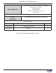
FIELD REPLACEMENT PROCEDURE TOOLS REQUIRED #1 and #2 Phillips screwdriver (Magnetic recommended) Small needle nose pliers Small wire cutters Electrical Tape ESD wrist strap with grounding cord Safety Glasses KIT P/N: FT HIGH BRIGHT LED STRIP W/ DRIVER KIT 06200-00185 PARTS SUPPLIED PART NUMBERS DESCRIPTION QUANTITY 09100-00445 High Bright LED Strip 2 09100-00444 LED Drive 1 This process will take approximately 45 minutes.
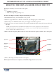
HIGH BRIGHT DISPLAY CCFL TO LED BACKLIGHT REPLACEMENT REMOVING THE DISPLAY ASSEMBLY FROM THE UNIT The Display Assembly is located on the control panel. Tools: 1 - #2 Phillips screwdriver 1 - ESD wrist strap with grounding cord. To remove the display assembly complete the following procedure: 1. Put the ESD wrist strap on and attach the cord to ground. 2. Perform a proper shutdown on the unit. Unlock and open the upper portion of the cabinet. 3.
FIELD REPLACEMENT PROCEDURE REMOVING THE DISPLAY FROM THE ASSEMBLY Tools: 1 - #2 Phillips screwdriver 1 - ESD wrist strap with grounding cord. To remove the display from the assembly, complete the following procedure: 1. Put the ESD wrist strap on and attach the cord to ground. 2. Remove the display assembly from the unit control panel per the previous instructions. 3. Carefully remove the glass cover from the display assembly, set aside. 4.
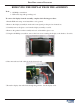
HIGH BRIGHT DISPLAY CCFL TO LED BACKLIGHT REPLACEMENT REPLACING THE CCFL INVERTER TO AN LED DRIVER BOARD Tools: 1 - ESD wrist strap with grounding cord. 1 - #1 Phillips screwdriver To replace the CCFL inverter to an LED driver board, complete the following procedure: 1. Put the ESD wrist strap on and attach the cord to ground. 2. Disconnect the inverter cable from the inverter. 3. Using the #1 Phillips screwdriver, remove the two screws securing the inverter to the bracket. Set aside. 4.
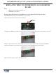
FIELD REPLACEMENT PROCEDURE REPLACING THE CCFL BACKLIGHTS WITH THE LED BACKLIGHTS IN AN APOLLO DISPLAY Tools: Apollo Display Triton Part Numbers 1 - ESD wrist strap with grounding cord 01160-00023 Display only 1 - Safety glasses 09200-00010 Assembly 1 - Small wire cutters 09200-00091 Assembly 1 - Small needle nose pliers 09200-00208 Assembly To replace the CCFL backlights with the LED backlights, complete the following procedure: 1. Put the ESD wrist strap on and attach the cord to ground.
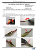
HIGH BRIGHT DISPLAY CCFL TO LED BACKLIGHT REPLACEMENT REPLACING THE CCFL BACKLIGHTS WITH THE LED BACKLIGHTS APOLLO DISPLAY cont... 7. Gently lift the two tubes out of the end of the rail using the pink wires. BE CAREFUL not to break the tubes as there is a small amount of mercury inside. 8. Using the small pliers, bend the end tab of the rail 90° to make it flush with the rail. Cut the wires as close to the tab as possible. Set the bulbs aside. 9. Bend the end tab of the rail back up to a 90° angle.
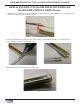
FIELD REPLACEMENT PROCEDURE REPLACING THE CCFL BACKLIGHTS WITH THE LED BACKLIGHTS APOLLO DISPLAY cont... 10. Remove any tape debris from the rail. 11. Obtain one LED strip. Peel the protective backing off the strip. Line up the end of the strip with the end tab of the rail. Slowly lower the strip into the rail putting light pressure on it to ensure the adhesive sticks to the rail. 12. Bend the tab covering the strip back into place. 13. Repeat steps 5 - 12 for the second rail. 14.
HIGH BRIGHT DISPLAY CCFL TO LED BACKLIGHT REPLACEMENT REPLACING THE CCFL BACKLIGHTS WITH THE LED BACKLIGHTS IN A OPTREX DISPLAY Tools: Optrex Display Triton Part Numbers 1 - ESD wrist strap with grounding cord 01160-00054 Display only 09200-10010 Assembly 1 - Safety glasses 09200-00326 Assembly 1 - Small needle nose pliers Electrical tape To replace the CCFL backlights with the LED backlights, complete the following procedure: 1. Put the ESD wrist strap on and attach the cord to ground.
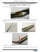
FIELD REPLACEMENT PROCEDURE REPLACING THE CCFL BACKLIGHTS WITH THE LED BACKLIGHTS OPTREX DISPLAY cont... 6. Pull the white wire towards the end of the bulb. Carefully lift the rubber stopper and bulbs out of the rail. BE CAREFUL not to break the tubes as there is a small amount of mercury inside. 7. On the other end, carefully pull the rubber stopper and bulbs out of the rail. Again, be careful not to break the tubes. Set the bulbs aside. 8. Obtain one LED strip.
HIGH BRIGHT DISPLAY CCFL TO LED BACKLIGHT REPLACEMENT REPLACING THE CCFL BACKLIGHTS WITH THE LED BACKLIGHTS OPTREX DISPLAY cont... 9. Repeat steps 6 - 8 for the second rail. 10. Slowly insert one LED rail into the backlight track until the locking latch clicks down into place. Repeat for the second LED rail. 10. Cut a 1 1/2 inch square piece of electrical tape. Without covering the display, install the tape on the front of the display and over the end of the rail to prevent light leakage.
FIELD REPLACEMENT PROCEDURE REINSTALLING THE DISPLAY INTO THE ASSEMBLY Tools: 1 - #2 Phillips screwdriver 1 - ESD wrist strap with grounding cord. To reinstall the display into the assembly, complete the following procedure: 1. Put the ESD wrist strap on and attach the cord to ground. 2. Connect the backlight cables to the driver board. 3. Ensure the display data cable is connected properly to the rear of the display. Route the cable out of the bracket through the grommet if previously removed.
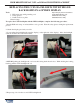
HIGH BRIGHT DISPLAY CCFL TO LED BACKLIGHT REPLACEMENT REINSTALLING THE DISPLAY INTO THE ASSEMBLY cont... 6. Obtain the previously removed display glass. Using a soft cloth and non-abrasive glass cleaner, carefully clean all smudges and debris off the glass. 7. Using the tabs on the bracket as guides, secure the glass in place with slight pressure. Ensure the glass is not covering the driver board as indicated below with the red box.