Automated Teller Machine Installation Manual TDN 07103-00338 Rev E. February 19, 2016 Corporate Headquarters: 21405 B Street Long Beach, MS. 39560 PHONE: (800) 259-6672 FAX: (228) 868-9445 © 2016 Triton. All Rights Reserved. TRITON logo is a registered trademark of Triton Systems of Delaware, LLC.
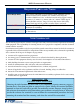
ARGO Installation Manual DOCUMENT UPDATES Date 2/19/13 3/3/13 3/25/13 4/8/13 4/10/15 2/19/16 8/27/18 Description Original Added intra-level bracket info Added installation of security bracket in lower cabinet Added “Replacing Older Units” info Added new drawings for ARGO 15 decal area Added updates for Relative Humidity requirements Updated temperature and humidity requirements 2
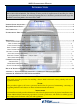
ARGO Installation Manual Introduction The Triton ARGO ATM is a lobby terminal designed for indoor use only. The ARGO line includes models RL1713, RL27XY, and RL63XY. The following sections provide the requirements for installing the ARGO for your particular site location. To assist in preparing your site, a check list is provided of various steps that should be carried out prior to the arrival of the ATM. Contents Purpose / Scope /Application................................................................
ARGO Installation Manual Required Parts and Tools TOOLS REQUIRED Torque wrench adjustable to at least 60 foot pounds, adjustable crescent wrench or ratchet wrench, hammer, 3/4” (19mm) socket, large flat screwdriver, bubble level, 7/16” socket/box wrench, safety goggles, hearing protection, 1/4” (6mm), 1/2: (12mm) and 9/16” (15mm) carbide-tipped masonry drill bits at least 6” long, 3/4” heavy-duty electric drill (rotaty hammer, back support belt, portable vaccuum cleaner, wire brush.
ARGO Installation Manual Environmental Precaution Checklist SITE PREPARATION CHECKLIST 1. Select site and design floor plan accordingly. 2. Ensure all environmental conditions are met. 3. Establish contractor and vendor schedules. 4. Check communication line requirements. 5. Plan installation and accessory needs before starting. 6. Check floor plan and make necessary alterations. 7. Install all required electrical fixtures. 8. Prepare site for communications needs. 9.
ARGO Installation Manual * IMPORTANT * AC power for the terminal should come from a dedicated source with an isolated ground. Dedicated Telephone Dedicated source - The ATM AC power feed will 3. Ensure the following telephone-line requirements are met: be a dedicated line, to which no other electrical devices are connected. The ATM power line will be wired for a single duplex-style outlet and connected directly to the AC service panel.
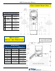
ARGO Installation Manual Deep Cabinet Front View Customer Access Dimensions Feature Height Top Function Key 2 #5 Key (Main Keypad) 3 Card Reader 47 5/16” [1202mm] 36 1/2” [928mm] 39 1/8” [994mm] 38 5/16” [974mm] 25 5/8” [651mm] 1 4 Receipt Printer 5 Bill Tray Deep Cabinet Service Area Dimensions 2” [51] clearance around cabinet sides and rear Dimensions Shown in inches/millimeters Dimension Business Hours Vault (Lvl 1) A 20 1/8” [510] 20 1/8” [510] B 27 7/8” [708] 28 1/4” [718] C 20 5/1
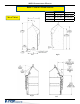
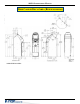
ARGO Installation Manual Deep Cabinet Dimensions Side Views Dimension Business Hours Vault (Lvl 1) H 22 1/8” [562] 22 9/16” [573] I 25 7/8” [658] 26 1/4” [667] J 9 11/16” [246] 26 1/4” [667] Right Left Right Left 8
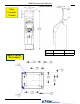
ARGO Installation Manual BACKLIT GRAPHIC Deep Cabinet Topper Deep Cabinet “Footprint” 9 Dimension Business Hours Vault (Lvl 1) K 6 9/16” [167] 7 1/16” [179]
ARGO Installation Manual Deep Cabinet Decal Area (Business hours) VISIBLE DECAL AREA 10
ARGO Installation Manual Triton Model argo 15 inch display SUGGESTED DECAL AREA 11
ARGO Installation Manual Deep Cabinet Decal Area (Vault) VISIBLE DECAL AREA SUGGESTED DECAL AREA 12
ARGO Installation Manual Shallow Cabinet Front View Customer Access Dimensions Feature Height Top Function Key 2 #5 Key (Main Keypad) 3 Card Reader 47” [1193mm] 36 1/2’’ [928mm] 39 1/8” [994mm] 38 5/16” [974mm] 25 5/8” [651mm] 1 4 Receipt Printer 5 Shallow Cabinet Service Area Dimensions 2” [51] clearance around cabinet sides and rear Dimensions Shown in inches/millimeters Dimension Business Hours A 20 1/16” [510] B 21 3/4” [553] C 16 15/16” [430] D 2 3/8” [60] E 26 7/8” [682] F 22” [5
ARGO Installation Manual Shallow Cabinet Dimensions (Business Hours) Side Views Right Left Right Left 14
ARGO Installation Manual Shallow Cabinet “Footprint” Shallow Cabinet Decal Area (Business hours) VISIBLE DECAL AREA 15
ARGO Installation Manual SUGGESTED DECAL AREA Replacing Older Units When replacing older Triton ATMs with the ARGO, you may be able to use holes already drilled to install the ATM. See the table below for corresponding hole sites.
ARGO Installation Manual Cabinet Installation The following procedure applies to installing the cabinet assembly using the standard (P/N 06200-00066) anchor kit. The anchor kit is not supplied with the unit. Call Triton at 888-7-ATMGURUS for availability. * IMPORTANT * The ARGO ATM is designed for INDOOR use only! **WARNING** DO NOT APPLY POWER TO THIS TERMINAL UNTIL THE INSTALLATION IS COMPLETE!! Unpack ATM 1.
ARGO Installation Manual Mark/Drill Mounting Holes Mark the location of the cabinet mounting holes on the concrete floor. This is accomplished as described below: 1. Move the ATM to the location where it will be installed. Open the cabinet vault door at least 90° to improve access. Locate the four (4) anchor-bolt holes in the bottom of the cabinet (each corner).
ARGO Installation Manual Install Standard Anchors/ Bolt ATM to Floor Locking Nut ARGO ATM Base Mounting Nut Flat washer Slab Anchor Bolt Anchor bolt installation illustration 1. Ensure the mounting location is free of all debris that might cause the cabinet to not be level. Use blower or vaccuum to remove any dust or particles. 2. Move the ATM into position for mounting by aligning the base over the four holes drilled in the previous procedure. 3.
ARGO Installation Manual Use anchor bolt in each mounting hole Hammer bolts snuggly into drilled holes 6. Ensure the cabinet is as level as possible given the floor conditions. Use a bubble level to verify this. If a bubble-level is not available, the cabinet can be “rocked” gently from front-to-back and side-to-side to check the need for leveling. 7. Use a torque wrench and 3/4” [19mm] socket to tighten each nut to 60 foot-pounds (required to establish the maximum pull-out strength of the anchors).
ARGO Installation Manual 1. Route the AC power cord and the phone (or Cat-5) cable through either the main or alternate cable access hole at rear corner of unit, (as applicable). 2. Connect the AC power cord and communication cable to their respective facility outlets. 3. Secure/plug the unused access hole with the grommet or plug provided. 4. Install the security bracket.
ARGO Installation Manual POWER SUPPLY CORD SPECIFICATIONS For European applications, the power supply cord must conform to the following: 1. Two-conductor with Physical Earth (PE) ground. 2. IEC 320 molded connector on one end and molded plug on the other end. 3. Certified for country of installation. 4. Rated minimum H05VV-F with minimum 0.75 mm2 (except where specific countries require 1.0 mm2) conductors. 5. Maximum length: 3 meters.
ARGO Installation Manual REFER TO THE USER MANUAL AND CONFIGURATION MANUAL FOR OPERATIONAL INSTRUCTIONS. NOTE: IT MAY TAKE UP TO 30 SECONDS FOR THE DISPLAY TO ILLUMINATE, AND ANOTHER 15 SECONDS FOR THE OPERATING SYSTEM TO LOAD.