AUTOMATED TELLER MACHINE INSTALLATION MANUAL TDN 07103-00053 CORPORATE HEADQUARTERS: 21405 B STREET LONG BEACH, MS 39560 PHONE: (800) 259-6672 FAX: (228) 868-9445 © 2014 Triton. All Rights Reserved. TRITON logo is a registered trademark of Triton Systems of Delaware, LLC.
ARGO G60 INSTALLATION MANUAL DOCUMENT UPDATES Date 01/30/14 Description Original ** WARNING ** Do NOT install the mechanism into the unit until the unit is bolted down to the ground. If the mechanism is installed prior to bolting the unit down, the unit could tip over and personal injury could occur. Follow the installation instructions in this manual to ensure the unit is properly installed and secured BEFORE installing the mechanism.
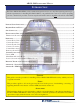
ARGO G60 INSTALLATION MANUAL INTRODUCTION The Triton ARGO G60 ATM is a lobby terminal designed for indoor use only. The following sections provide the requirements for installing the ARGO G60 for your particular site location. To assist in preparing your site, a check list is provided of various steps that should be carried out prior to the arrival of the ATM. CONTENTS PURPOSE / SCOPE / APPLICATION.............................................................................................................
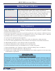
ARGO G60 INSTALLATION MANUAL REQUIRED PARTS AND TOOLS TOOLS REQUIRED Torque wrench adjustable to at least 60 foot pounds, adjustable crescent wrench or ratchet wrench, hammer, 3/4” (19mm) socket, large flat screwdriver, bubble level, 7/16” socket/box wrench, safety goggles, hearing protection, 1/4” (6mm), 1/2: (12mm) and 9/16” (15mm) carbide-tipped masonry drill bits at least 6” long, 3/4” heavy-duty electric drill (rotaty hammer, back support belt, portable vaccuum cleaner, wire brush.
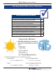
ARGO G60 INSTALLATION MANUAL ENVIRONMENTAL PRECAUTION CHECKLIST SITE PREPARATION CHECKLIST 1. Select site and design floor plan accordingly. 2. Ensure all environmental conditions are met. 3. Establish contractor and vendor schedules. 4. Check communication line requirements. 5. Plan installation and accessory needs before starting. 6. Check floor plan and make necessary alterations. 7. Install all required electrical fixtures. 8. Prepare site for communications needs. 9.
ARGO G60 INSTALLATION MANUAL * IMPORTANT * AC power for the terminal should come from a dedicated source with an isolated ground. DEDICATED TELEPHONE Dedicated source - The ATM AC power feed will 3. Ensure the following telephone-line requirements are met: be a dedicated line, to which no other electrical devices are connected. The ATM power line will be wired for a single duplex-style outlet and connected directly to the AC service panel.
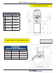
ARGO G60 INSTALLATION MANUAL CABINET FRONT VIEW Customer Access Dimensions Feature Height Top Function Key 2 #5 Key (Main Keypad) 3 Card Reader 46 15/16” [1193mm] 36 1/2” [928mm] 39 1/16” [992mm] 38 1/4” [972mm] 27 3/16” [690mm] 1 4 Receipt Printer 5 Bill Tray CABINET SERVICE AREA DIMENSIONS Dimensions i i Shown in inches/millimeters Dimension Preferred Area Minimum Area A 26” [660] 24 1/2” [622] B 33 9/16” [853] 31 1/2” [799] C 21 3/8” [542] 21 15/16” [558] D 12 3/4” [324] 10 5/8” [
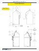
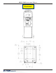
ARGO G60 INSTALLATION MANUAL CABINET DIMENSIONS SIDE VIEWS Right Left Right Left 8
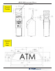
ARGO G60 INSTALLATION MANUAL BACKLIT GRAPHIC CABINET TOPPER Front Side CABINET SIGN AREA 9 Rear
ARGO G60 INSTALLATION MANUAL CABINET “FOOTPRINT” 10
ARGO G60 INSTALLATION MANUAL CABINET DECAL AREA VISIBLE DECAL AREA SUGGESTED DECAL AREA 11
ARGO G60 INSTALLATION MANUAL REPLACING OLDER UNITS When replacing older Triton ATMs with the ARGO G60, you may be able to use holes already drilled to install the ATM. See the table below for corresponding hole sites.
ARGO G60 INSTALLATION MANUAL CABINET INSTALLATION The following procedure applies to installing the cabinet assembly using the standard (P/N 06200-00066) anchor kit. The anchor kit is NOT supplied with the unit. Call Triton at 888-7-ATMGURUS for availability.
ARGO G60 INSTALLATION MANUAL UNPACK ATM 1. Carefully inspect the shipping container for any damage and report any damage immediately to the shipping company. Refer to the warranty information in the User Manual for information about reporting shipping damage. 2. Remove the ATM cabinet from the carton by cutting the straps and removing the top of the box. Combination Locks Mechanical Lock: There are two marks on the dial ring. The index mark at the top of the dial is used for opening the lock.
ARGO G60 INSTALLATION MANUAL Mark/Drill Mounting Holes Mark the location of the cabinet mounting holes on the concrete floor. This is accomplished as described below: 1. Move the ATM to the location where it will be installed. Open the cabinet vault door at least 90° to improve access. Locate the four (4) anchor-bolt holes in the bottom of the cabinet (each corner).
ARGO G60 INSTALLATION MANUAL INSTALL STANDARD ANCHORS/ BOLT ATM TO FLOOR LOCKING NUT ARGO ATM BASE MOUNTING NUT FLAT WASHER SLAB ANCHOR BOLT Anchor bolt installation illustration 1. Ensure the mounting location is free of all debris that might cause the cabinet to not be level. Use blower or vaccuum to remove any dust or particles. 2. Move the ATM into position for mounting by aligning the base over the four holes drilled in the previous procedure. 3.
ARGO G60 INSTALLATION MANUAL Use anchor bolt in each mounting hole Hammer bolts snuggly into drilled holes 6. Ensure the cabinet is as level as possible given the floor conditions. Use a bubble level to verify this. If a bubble-level is not available, the cabinet can be “rocked” gently from front-to-back and side-to-side to check the need for leveling. 7. Use a torque wrench and 3/4” [19mm] socket to tighten each nut to 60 foot-pounds (required to establish the maximum pull-out strength of the anchors).
ARGO G60 INSTALLATION MANUAL 1. Route the AC power cord and the phone (or Cat-5) cable through either the main or alternate cable access hole at rear corner of unit (as applicable). 2. Connect the AC power cord and communication cable to their respective facility outlets. 3. Secure/plug the unused access hole with the grommet or plug provided. 4. Install the security bracket.
ARGO G60 INSTALLATION MANUAL POWER SUPPLY CORD SPECIFICATIONS For European applications, the power supply cord must conform to the following: 1. Two-conductor with Physical Earth (PE) ground. 2. IEC 320 molded connector on one end and molded plug on the other end. 3. Certified for country of installation. 4. Rated minimum H05VV-F with minimum 0.75 mm2 (except where specific countries require 1.0 mm2) conductors. 5. Maximum length: 3 meters.
APPENDIX A SOFTWARE LICENSE AGREEMENT COMPLIANCE / EMISSION STATEMENTS
APPENDIX A - SOFTWARE LICENSE AGREEMENT / COMPLIANCE/EMISSION STATEMENTS AUTOMATED TELLER MACHINE (“ATM”) SOFTWARE END-USER AGREEMENT IMPORTANT: PLEASE READ CAREFULLY: BY INSTALLING OR OTHERWISE USING THE ATM, YOU (AS THE OWNER OR LESSEE OF THE ATM).
APPENDIX A - SOFTWARE LICENSE AGREEMENT / COMPLIANCE/EMISSION STATEMENTS DISCLAIMER OF WARRANTIES AND LIMITATION OF DAMAGES TO THE EXTENT PERMITTED BY LAW, THIS ATM SOFTWARE, INCLUDING ALL INCORPORATED THIRD PARTY SOFTWARE, AND DERIVATIVES IS PROVIDED, “AS IS”. TRITON MAKES NO REPRESENTATIONS WITH RESPECT TO, AND DOES NOT WARRANT THE PERFORMANCE OR RESULTS YOU OR YOUR CUSTOMERS MAY OBTAIN BY USING THE ATM.
APPENDIX A - SOFTWARE LICENSE AGREEMENT / COMPLIANCE/EMISSION STATEMENTS COMPLIANCE / EMISSION STATEMENTS DISCLAIMER The manufacturer of the Automated Teller Machine (ATM) product(s) described herein makes no representations or warranties, either expressed or implied, by or with respect to anything in this manual, and shall not be liable for any implied warranties of fitness for a particular purpose or for any indirect, special, or consequential damages.
Appendix B ATM Installation for Accessibility
Appendix B - ATM Installation for Accessibility A Guide to the ADA Guidelines 305. Clear Floor or Ground Space 305.1 General. Clear floor or ground space shall comply with 305. 305.2 Floor or Ground Surfaces. Floor or ground surfaces of a clear floor or ground space shall comply with 302. Changes in level are not permitted. EXCEPTION: Slopes not steeper than 1:48 shall be permitted. 305.3 Size. The clear floor or ground space shall be 30 inches (760 mm) minimum by 48 inches (1220 mm) minimum.
Appendix B - ATM Installation for Accessibility 308. Reach Ranges 308.1 General. Reach ranges shall comply with 308. 308.2 Forward Reach. 308.2.1 Unobstructed. Where a forward reach is unobstructed, the high forward reach shall be 48 inches (1220 mm) maximum and the low forward reach shall be 15 inches (380 mm) minimum above the finish floor or ground. Figure 308.2.1 Unobstructed Forward Reach 308.2.2 Obstructed High Reach.
Appendix B - ATM Installation for Accessibility 308.3.2 Obstructed High Reach. Where a clear floor or ground space allows a parallel approach to an element and the high side reach is over an obstruction, the height of the obstruction shall be 34 inches (865 mm) maximum and the depth of the obstruction shall be 24 inches (610 mm) maximum. The high side reach shall be 48 inches (1220 mm) maximum for a reach depth of 10 inches (255 mm) maximum.
Appendix B - ATM Installation for Accessibility (a) Reach Depth Not More Than 10 inches (255 mm). Where the reach depth to the operable parts of all controls as measured from the vertical plane perpendicular to the edge of the unobstructed clear floor space at the farthest protrusion of the automated teller machine or surround is not more than 10 inches (255 mm), the maximum height above the finished floor or grade shall be 54 inches (1370 mm). b) Reach Depth More Than 10 inches (255 mm).
Appendix B - ATM Installation for Accessibility 4.2.4 Clear Floor or Ground Space for Wheelchairs. 4.2.4.1 Size and Approach. The minimum clear floor or ground space required to accommodate a single, stationary wheelchair and occupant is 30 inches by 48 inches (760 mm by 1220 mm) (see Fig.4a). The minimum clear floor or ground space for wheelchairs may be positioned for forward or parallel approach to an object (see Fig. 4b and 4c).
Appendix B - ATM Installation for Accessibility Figures 4d. Clear Floor Space in Alcoves. Figures 4e. Clear Floor Space in Alcove. For a side approach, where the depth of the alcove is equal to or less than 15 inches (380 mm), the required clear floor space is 30 inches by 48 inches (760 mm by 1220 mm).
Appendix B - ATM Installation for Accessibility 4.2.6 Side Reach. If the clear floor space allows parallel approach by a person in a wheelchair, the maximum high side reach allowed shall be 54 inches (1370 mm) and the low side reach shall be no less than 9 inches (230 mm) above the floor (Fig. 6(a) and 6(b)). If the side reach is over an obstruction, the reach and clearances shall be as shown in Fig 6(c). Figure 6b. Parallel approach - high/low side reach. Figure 6a. Parallel approach - side reach.