
Owner Manual

9600-TO-9650 CONVERSION GUIDE
4
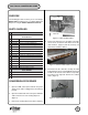
8. Pivot the power supply plate down and disconnect
the Phone Line In cable from the connector labeled
J1 on the surge protector board. Disconnect the
phone line to backplane cable from the connector
on the backplane labeled J5. Disconnect the power
supply cable connector. Remove the 9600 Power
Supply Assembly from the unit. Disconnect the
9600 Dispenser Power Cable plugged into J9 and
remove the cable from the unit.
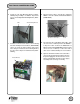
9. Plug the 9650 Dispenser Power Cable (09800-
00019) into the connector labeled J9 on the
backplane. There is a polarizing pin on the
connector, so make sure that the connector is
properly aligned with the mating connector on the
backplane before proceed. Route the end of the
cable into the cabinet through the oval slot in the
top of the cabinet. Snap the Ferrite Clip onto the
cable next to the backplane connector.
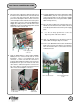
13. Slide the 9650 Dispenser Mechanism into the
cabinet while viewing the dispenser cables.
14. Connect the 9650 DC Power Cable and EJ Data
Cable to the left side of the dispenser mechanism.
Note: The EJ data cable is connected to the most
forward connector.
Dispenser
Power Cable
Route end of cable through hole
in the cabinet
DC Power Connection
EJ Communication Data
Cable
10. Install the 9650 European Power Supply Assembly
( 09600-02087) into the card cage. Reverse the
steps in Step 8. Make sure the new Power Supply
being installed has the correct part number. ( 9600-
2087 is European P.S.)
11. Close the power supply to the card cage and secure
with the 2 screws. Reconnect the cables connected
to the AC input module located on the power supply
plate.
J5
Powr supply cable
connector
J9
J1
12. Use the tie wraps provided to secure the
dispenser power cable to the cabinet.