SPEECH JACK INSTALLATION GUIDE PCI KEYPAD UPGRADE COMPLETED (MODEL 96XX) TDN 07103-08205-00 March 27, 2012 CORPORATE HEADQUARTERS: 21405 B STREET LONG BEACH, MS 39560 PHONE: (800) 259-6672 FAX: (228) 868-9445 RMA (RETURN MATERIAL AUTHORIZATION) RETURN ADDRESS: 21405 B STREET LONG BEACH, MS 39560 © 2012 Triton. All Rights Reserved.
SPEECH INSTALLATION GUIDE Updates: April 4, 2011 original September 28, 2011 picture edits March 27, 2012 picture edits * NOTE * This instruction is to be used for the installtion of the speech jack on 96xx units that have had the PCI Keypad (oyster) kit upgrade completed. There should be no software nor circuit board replacement requirement. ** Important ** The upgrade procedures may require removal and replacement of electrostatic sensitive devices such as integrated circuits, boards, and assemblies.
SPEECH INSTALLATION GUIDE INTRODUCTION This guide covers the steps for installing a speech (headphone jack) kit for Model 96XX ATMs. This procedure includes a list of tools and hardware required for the upgrade as well as the steps involved. SCOPE This procedure applies to all service personnel involved in the process of maintaining or converting Triton ATMs.
SPEECH INSTALLATION GUIDE Installation Follow these steps to install the speech installation kit for the Model 96XX ATM: * Important * When routing the headphone cables in the control panel, it is critical that cables are isolated from the main ribbon cable that runs from the card cage to the keypad. DO NOT ROUTE/SECURE HEADPHONE CABLE WITH THIS RIBBON CABLE! 1. Unlock and open the control panel. Verify that the power switch is in the OFF (0) position. Close the control panel. 2.
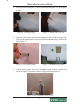
SPEECH INSTALLATION GUIDE 3. Drill a pilot hole using the 1/8” drill bit and finish using the 7/16" bit (Figures 4 and 5). Figure 4. Drill pilot hole. 4. Figure 5. Finish with 7/16" bit. Open the control panel and feed the headphone cable (audio jack side first, Figure 6) through the hole (exterior) until the headphone plug is flush in the hole (Figure 7). Figure 6. Feed cable in hole. 5. Figure 7. Headphone plug flush.
SPEECH INSTALLATION GUIDE 6. Using a 7/16" nutdriver, remove the bolt shown in Figure 9. Install the ground wire adapter and secure with bolt previously removed (Figure 10). Connect the ground wire from the headphone cable to this adapter. Figure 9. Remove bolt. 7. Figure 10. Install ground wire adapter. Install an extruded wire harness clip to the speaker screw shown in Figure 11. Route the cable under and through the clip so cable has a “bow”.
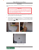
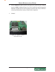
SPEECH INSTALLATION GUIDE 8. Pull the Memory module from the card cage (SS-2) and verify the EPROM version is 04.01 or higher (Figure 14). If not, install the required upgraded EPROM (included in kit) following ESD precautions and correct orientation of the chip. Reinstall the memory module after completion. 9. Omitted Figure 14. Memory module EPROM location.
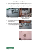
SPEECH INSTALLATION GUIDE 10. Open the ferrite included in kit. Wrap the headphone cable in the ferrite as shown in Figure 17. Position the ferrite as close as possible to the headphone jack and snap ferrite together. Plug the headphone jack into the jack provided on the Tri-Port/Speech module shown in Figure 18. Figure 17. Install cable in ferrite. Figure 18. Connect cable to Multi function board. 11. Secure any excess cable to the cable clip shown in Figure 19. 12.