
Owner Manual


7
MULTIFUNCTION/SPEECH INSTALLATION GUIDE
9. Step nine omitted
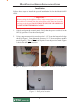
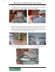
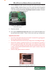
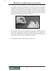
8. Pull the Memory module from the card cage (SS-2) and verify the EPROM
version is 04.01 or higher (Figure 14). If not, install the required upgraded
EPROM (included in kit) following ESD precautions and correct orientation
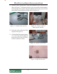
of the chip (see pages 8 and 9 for Chip Replacement Procedures). Reinstall
the memory module after completion.
Figure 14. Memory module
EPROM location.
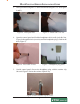
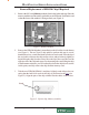
10. The required Multi-function/Speech module will be installed in slot 4 (SS-4)
beneath the Modem module. Figure 16 shows the card cage configuration.
IMPORTANT NOTES:
• Port ONE of the Multi-function board is ONLY for the PCI keypad upgrade.
Do not plug anything else into this port.
• The Multi-function board will NOT provide power to a scrolling LED sign.
• Remove the memory expansion board, as it is not required. If you have a
memory expansion module, and wish to retain it, move jumper J1 & J2 to pins
2-3 (Aux 2) as shown on the circuit card. Place the expansion module in slot
5 (SS5). AFTER SOFTWARE DOWNLOAD. Figure 16 below shows the
module installed.
• Software and graphics must be reloaded.
Figure 16. Card cage configured.