MODEL 96XX SPEECH INSTALLATION GUIDE PCI KEYPAD NOT INSTALLED TDN 07103-10023-00 March 27, 2012 CORPORATE HEADQUARTERS: 21405 B STREET LONG BEACH, MS 39560 PHONE: (800) 259-6672 FAX: (228) 868-9445 RMA (RETURN MATERIAL AUTHORIZATION) RETURN ADDRESS: 21405 AVENUE “B” LONG BEACH, MS 39560 © 2012 Triton. All Rights Reserved.
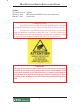
MULTIFUNCTION/SPEECH INSTALLATION GUIDE Updates: November 30, 2011 Original. March 15, 2012 Edits to clarify EPROM access code requirement. March 27, 2012 picture edits * WARNING NOTE * • The 9XXX Software required with this upgrade may be obtained from the Triton partner web site. Always use the latest version of software. • You must have your EPROM access code to load software. DO NOT begin the hardware installation without this code.
MULTIFUNCTION/SPEECH INSTALLATION GUIDE INTRODUCTION This guide covers the steps for installing a speech (headphone jack) kit for Model 96XX ATMs. It is independent of the PCI keypad upgrade. This procedure includes a list of tools and hardware required for the upgrade as well as the steps involved. SCOPE This procedure applies to all service personnel involved in the process of maintaining or converting Triton ATMs.
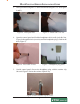
MULTIFUNCTION/SPEECH INSTALLATION GUIDE Installation Follow these steps to install the speech installation kit for the Model 96XX ATM: * Important * When routing the headphone cables in the control panel, it is critical that cables are isolated from the main ribbon cable that runs from the card cage to the keypad. DO NOT ROUTE/SECURE HEADPHONE CABLE WITH THIS RIBBON CABLE! 1. Unlock and open the control panel. Verify that the power switch is in the OFF (0) position. Close the control panel. 2.
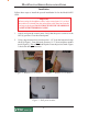
MULTIFUNCTION/SPEECH INSTALLATION GUIDE 3. Drill a pilot hole using the 1/8” drill bit and finish using the 7/16" bit (Figures 4 and 5). Figure 4. Drill pilot hole. 4. Figure 5. Finish with 7/16" bit. Open the control panel and feed the headphone cable (audio jack side first, Figure 6) through the hole (exterior) until the headphone plug is flush in the hole (Figure 7). Figure 6. Feed cable in hole. 5. Figure 7. Headphone plug flush.
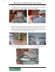
MULTIFUNCTION/SPEECH INSTALLATION GUIDE 6. Using a 7/16" nutdriver, remove the bolt shown in Figure 9. Install the ground wire adapter and secure with bolt previously removed (Figure 10). Connect the ground wire from the headphone cable to this adapter. Figure 9. Remove bolt. 7. Figure 10. Install ground wire adapter. Install an extruded wire harness clip to the speaker screw shown in Figure 11. Route the cable under and through the clip so cable has a “bow”.
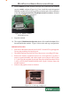
MULTIFUNCTION/SPEECH INSTALLATION GUIDE 8. Pull the Memory module from the card cage (SS-2) and verify the EPROM version is 04.01 or higher (Figure 14). If not, install the required upgraded EPROM (included in kit) following ESD precautions and correct orientation of the chip (see pages 8 and 9 for Chip Replacement Procedures). Reinstall the memory module after completion. Figure 14. Memory module EPROM location. 9. Step nine omitted 10.
MULTIFUNCTION/SPEECH INSTALLATION GUIDE 11. Open the ferrite included in kit. Wrap the headphone cable in the ferrite as shown in Figure 17. Position the ferrite as close as possible to the headphone jack and snap ferrite together. Plug the headphone jack into the jack provided on the Multi-function/Speech module shown in Figure 18. Figure 17. Install cable in ferrite. Figure 18. Connect cable to Multi-function module. 12. Secure any excess cable to the cable clip shown in Figure 19. 13.
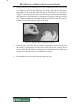
MULTIFUNCTION/SPEECH INSTALLATION GUIDE Removal/Replacement of EPROM Chip if Required 1. Remove the SS-2 card (Memory module) from its slot in the card cage. Place the memory module on a flat surface (preferably on an ESD mat). Position the card so that the front of the module is facing towards you (Figure 1). Remove this chip Figure 1. Memory module. 2. Remove the EPROM chip that is immediately to the left of the circular battery (see Figure 1).
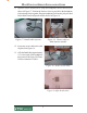
MULTIFUNCTION/SPEECH INSTALLATION GUIDE 4. It may be necessary to bend the pins on one or both edges of the chip inward very slightly to achieve this alignment. To do this, grasp the left and righthand edges of the chip and orient the chip so that the pins are facing you (Figure 3). Place the pins on one side of the chip on a flat surface and apply mild pressure to bend the pins by angling the top edge of the chip toward you. Check the alignment of the pins with the socket as before.
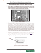
MULTIFUNCTION/SPEECH INSTALLATION GUIDE SOFTWARE DOWNLOAD The terminal software must be loaded using the TriComm for Windows® executable program found on the Triton partner web site, along with the latest 9600 software. The following procedures describe accessing the terminal Eprom Diagnostic screen and running the TriComm for Windows program. * IMPORTANT * The EPROM chip and all associated hardware required must be installed and the EPROM must be erased prior to downloading the operating software.
MULTIFUNCTION/SPEECH INSTALLATION GUIDE ** WARNING ** This selection will erase part of the unit’s memory and should be used only with caution! Enter the erase code to proceed or cancel to end. 4. Enter the Erase Program code of 2455. When the erase operation is completed the main menu will appear. 5. Press the ERASE EEPROM option. A warning screen is displayed, as in step 3. 6. Enter the Erase EEPROM code of 2455. When the erase operation is completed the main menu will appear. 7.
MULTIFUNCTION/SPEECH INSTALLATION GUIDE 2. Unlock and open the control panel of the terminal. Connect the other end of the download cable to the load port located on the CPU module shown below. Load Port (CPU) CONFIGURE TRICOMM FOR WINDOWS PROGRAM 1. Install the TriComm application onto your PC. . 2. Access the Windows Start\Programs menu and select the TriComm option. Select the WTriComm.exe. file. The program will start. The program’s main window will be displayed: 3. Click the Settings button.
MULTIFUNCTION/SPEECH INSTALLATION GUIDE 4. Choose a Com Port setting that matches the port on the PC. Click the down arrow on the Com Port control to see additional selections, as shown here: 5. Use the Drive List control to select the location of the software file you downloaded from Triton and extracted.
MULTIFUNCTION/SPEECH INSTALLATION GUIDE 6. Below is representative of file location. 7. The File List box will show the contents of the currently selected directory on the drive. Here is an example of a file name, this one is for a 9100 ATM: 8. The kinds of load files that will be displayed in the list will depend upon the ATM model type and the type of load file (Full Load or Update Load) present on the disk.
MULTIFUNCTION/SPEECH INSTALLATION GUIDE Start Software Download 1. Click the Load button on the TriComm main window. The software loading process begins. The Percent Completed progress bar will indicate the degree of completion of the file transfer. A corresponding progress indicator will appear on the terminal display during the file transfer, along with the words, “TRANSFER INITIATED.” 2.