
Owner Manual

3-3
9600
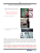
This section updates the EPROM chip on the Memory Module in slot 2 (two).
Before beginning, ensure you are working in a non-conductive anti-static environment. Ensure you are properly grounded
through the use of an approved ant-static grounding wrist strap. Handle the EPROM with extreme care. Make every attempt
not to touch the EPROM pins. When installing the new EPROM, pay close attention to the orientation of the chip in its
socket and make sure none of the pins are bent after installation. A little extra care now will avoid problems later.
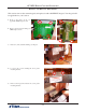
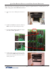
1.
Remove the Memory Module from slot 2 (two) and
place it on a non-conductive anti-static surface. ( the
Multifunction board bag will do in a pinch)
2.
This is representative of the EPROM (U1) to be
removed.
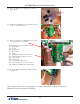
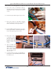
5. Install the Memory Module back into slot 2 (two).
Secure with the locking pins.
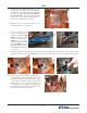
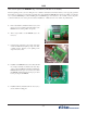
3.
Using the chip extraction tool provided, grasp each
end of the EPROM and pull up using even, rm,
constant pressure. Ensure you are pulling on the
chip and not the socket.
4. Install the new EPROM into the socket. Note the half
moon shape at the left end, matches the same shape
on the socket. Be VERY careful when installing the
EPROM. Ensure the pins do not bend out or under
the EPROM, and that each pin is in the proper socket
before pressing in the EPROM.