
Owner Manual


2-4
PCI EPP KEyPad UPgradE ProCEdUrEs
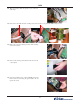
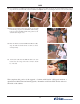
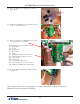
11. Secure the cables to the retaining plate with the ty
wrap provided.
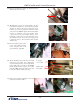
12. Install the new SPED adaptor board with 4 (four) long
screws. (8-32 x 1/2 inch bag 1)
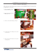
14. Ty wrap the keypad communications cable to the lower
right standoff.
This completes this portion of the upgrade. Continue with Section 3 (Quad Port Board to
Multi-Function Board Upgrade and cabling).
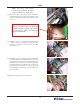
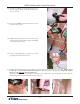
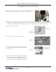
13. Reconnect all cables to the SPED adaptor board. The
new keypad cable connects to J12.
From the upper left (circle) counter clockwise.
J5 Printer Reset
J8 Inverter
J10 Right Keypad
J3 Printer Data
J1 Blank
J4 Card Reader (Blank for Canada only)
P6 Card Cage (Bottom ribbon connector)
J9 Audio speaker
J12 New Keypad
J6 Mono Display (Cable shown)
J7 Color Display (Connector next to mono)
J11 Left Keypad (Hidden under display cable)