
Owner Manual

1-9
9600
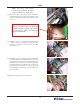
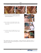
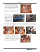
34. Use a nut driver to install the threaded standoff (yours will be longer than shown) into the insert installed in the previous
step. Ensure the standoff is fully seated, but do not over tighten. Chance of breaking the threads on the stand off are high.
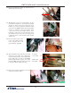
35. Place the card reader ground straps, and the ground cable
from the hinge (step 32) onto the ESD module mounting
hole and secure the ESD module and grounds to the
standoff with a single screw.
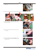
36. Place the Ferrite around the EMV Card Reader cable,
wrap the cable around the ferrite one time as shown,
and snap rmly.
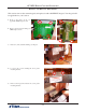
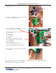
This completes this portion of the upgrade. Continue with Section 2 (Keypad) and then 3
(Quad Port to Multi-Function Board Upgrade). Remember to afx the EMV license sticker to
the inside of the cabinet.
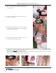
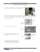
37. Connect the cable from the ESD module to the card
reader. Note: the orange wire in the connector should
be on the left.