
Owner Manual

1-5
9600
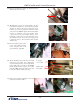
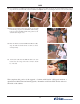
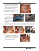
16. Install the 2 (two) screws into the lower printer bracket
a couple of turns. Do not tighten. It will take some
pushing and jiggling to ensure all 6 (six) mounting
holes line up.
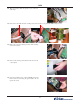
17. Install the 2 (two) screws and clips into the piston bracket
a couple of turns. Do not tighten. Push the clips to the
side to allow access to the lower printer bracket screws.
After all 6 (six) screws have been started, tighten the
top printer bracket screws (shown in step 15) and lower
printer bracket screws (shown in step 16). Leave the
screws holding the plastic clips loose (but make sure
they are started).
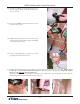
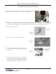
Note: When the brackets are aligned
properly, the piston bracket is ush with
the printer bracket, (plastic clips and ca-
bles removed for clarity) and the paper
bracket is underneath.
18. Tighten the pneumatic piston bracket bolt.
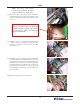
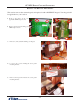
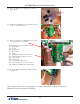
15. Now, remove the 2 (two) upper screws securing the
printer bracket to the control panel, previously loosened
in step 12. Install 2 (two) longer screws but leave them
very loose.
Note: Use the 6 (six) longer
screws (8-32 X 1/2 inch) provided
(bag 2) for the next 3 (three) steps.