9600 PCI EPP Keypad and Card Reader Upgrade TDN 07103-08200 Feb 11, 2011 This upgrade requires software updates for both Canada and the US. Refer to page 6 in this manual and the Triton web site for the required software. Corporate Headquarters 21405 B Street Long Beach, Ms. 39560 Phone: (800) 259-6672 Fax: (228) 868-9445 COPYRIGHT NOTICE © 2010 Triton. All Rights Reserved.
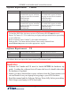
PCI EPP and Card Reader Upgrade Procedures Document Updates March 10, 2010 March 30, 2010 April 2, 2010 April 5, 2010 Feb 11, 2011 Original Revised software requirements, added warning on software load order. pg 6. Revised warnings on page 6. Added Canada mono display software on pg 6.
Introduction Introduction Section 1 Section 2 Section 3 Table of Contents ............................................................................................................................ 3 EMV Card Reader Replacement (Canada Only)..................................... 1-1 PCI EPP Replacement .............................................................................. 2-1 Quad Port Board Replacement with Multi-Function Board.................
PCI EPP and Card Reader Upgrade Procedures Additional Notes: CreditCall Sticker (CANADA ONLY) Upon completion of your particular upgrade procedure, affix the CreditCall sticker to a prominent place on the inside of the cabinet. (On the left side wall in front of the card cage is recommended.
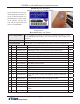
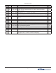
Introduction US CAN Part # X 09120-00013 X X X X 02318-00000 02323-00001 01030-00010 02054-00166 X X 03072-00009 03072-00015 X X X X 02054-00300 02303-00007 03011-00047 02321-00000 Description Bag of parts #2 4x6 in Cable, Power Supply Backplate to Cabinet Ground, 10AWG Braid, 8 inch Standoff |#8-32 | x 3/4 inch | Hex, Brass Insert, threaded, #8-32 Thread, 7/32 hole size, snap-in, no flange Ferrite | ROHS Screw | #8-32 x 1/2 inch | Pan Phil Head w/Ext Tooth Wash | ROHS Clip | Panduit Adhesive Cabl
PCI EPP and Card Reader Upgrade Procedures Software Requirements Model 9600 9600 Canada Full Load Software Version XD890076.00 (Color display) To enable EMV support, the following plug-ins must also be installed: EMVK0000.B96 EMVA0000.B96 XD880076.00 (Monochrome display) To enable EMV support, the following plug-ins must also be installed: EMVK0000.B96 EMVA0000.B96 Update Software Version XAT-8976.00 (Color display) To enable EMV support, the following plug-ins must also be installed: EMVK0000.
Section 1 EMV Card Reader Upgrade 9600 Canada Only
EMV Card Reader Upgrade Procedures 9600 Remove and Replace Procedures You may have upgraded to the EMV Card Reader in a previous upgrade. Go through these steps as a quality check. The EMV card reader in this kit may be newer than the one you have. Retain all hardware, (screws, nuts bolts) some will be reused. Before proceeding, follow these steps to remove power from the ATM: Unlock and open the ATM control panel.
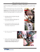
600 6. Disconnect the cable connectors at J3 (Printer) and J5 (Printer-Reset) on your applicable keypad adapter board. 7. Remove the ribbon cable from between the adhesive cable clips 8. Disconnect the low paper sensor cable at connector J11 on the printer control board. This cable is connected to the low paper sensor on the paper roll bracket. 9. Remove the low paper sensor bracket from the paper roll bracket. It may be held on with hex screws or Philips head screws. You may have one of two types.
EMV Card Reader Upgrade Procedures 10. Loosen the bolt on the pneumatic piston bracket. 11. Remove the 2 (two) screws securing the paper bracket to the printer bracket. 12. Loosen but do not remove the 2 (two) upper screws securing the printer bracket to the control panel. 13. Move the disconnected cables aside as needed. Lift the printer bracket slightly and slide the paper bracket from beneath the printer bracket and pneumatic piston bracket. Remove the paper bracket. 14.
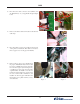
9600 Note: Use the 6 (six) longer screws (8-32 X 1/2 inch) provided (bag 2) for the next 3 (three) steps. 15. Now, remove the 2 (two) upper screws securing the printer bracket to the control panel, previously loosened in step 12. Install 2 (two) longer screws but leave them very loose. Note: When the brackets are aligned properly, the piston bracket is flush with the printer bracket, (plastic clips and cables removed for clarity) and the paper bracket is underneath. 16.
EMV Card Reader Upgrade Procedures 19. Place the pneumatic piston back onto its bolt and secure with the nut removed earlier. 20. Reattach the low paper sensor and bracket to the new paper bracket with 2 (two) screws. Ensure the plastic washers are between the paper bracket and sensor bracket. If your new bracket has shoulders around each screw hole, OMIT the plastic washers. The plastic washers, or shoulders on the paper bracket, create a space between the paper bracket and the sensor bracket.
9600 24. Place the ribbon cable through the 2 (two) adhesive cable clips. 25. Remove the data cable from the existing card reader and J4 of your particular SPED adaptor board. 26. Remove the 4 (four) mounting screws from the existing card reader. (retain) 27. Remove the existing card reader from the front of the control panel. 28. Note the grounding wires on the new EMV card reader. Remove the screw securing the ground cables. Do not replace the screw.
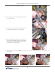
EMV Card Reader Upgrade Procedures 29. Insert the new EMV card reader through the front of the control panel. Ensure the printed circuit board is on top, as shown. 30. Secure the new EMV card reader with 4 (four) screws from previous step. (26) 31. Install the grounding strap as shown. Use the open end wrench for the bolt on the cabinet, and the short Philips screwdriver for the card cage. 32. Connect a grounding strap to the left corner control panel hinge bolt (near the card reader). 33.
9600 34. Use a nut driver to install the threaded standoff (yours will be longer than shown) into the insert installed in the previous step. Ensure the standoff is fully seated, but do not over tighten. Chance of breaking the threads on the stand off are high. 35. Place the card reader ground straps, and the ground cable from the hinge (step 32) onto the ESD module mounting hole and secure the ESD module and grounds to the standoff with a single screw. 36.
EMV Card Reader Upgrade Procedures Low Receipt-paper Sensor Upgrade If you have a type one low paper sensor, you should be here from step 20. If it looks like the sensor and bracket to the right, you are in the right place. 1. With the sensor and bracket removed from the paper bracket, push the plastic rivets, holding the sensor to the bracket, out from the sensor side. The handle of a screw driver may be used to push the rivet. It is in 2 (two) parts, much like a lag bolt.
Section 2 PCI EPP Keypad Upgrade 9600
PCI EPP Keypad Upgrade Procedures Remove and Replace Procedures This section removes the current keypad, and replaces it with a PCI EPP T7 keypad. Your key pad will be applicable for your location. 1. Remove all cables from your applicable SPED adaptor board. 2. Remove 4 (four) screws holding your SPED adaptor board. 3. Remove 4 (four) standoffs holding your keypad. 4. Loosen 2 (two) screws holding the screen panel mounting bracket. 5. Remove the keypad from under the screen panel mounting bracket.
9600 6. Install the keypad retaining plate with the 4 (four) short standoffs. Start all 4 (four) before tightening. It may take a few attempts before all 4 (four) standoffs are started properly. DO NOT CROSS THREAD THE STANDOFFS. Note the retaining bracket mounts on top of the screen mounting bracket. Use the nut driver to tighten these standoffs. 7. Tighten the 2 (two) screws in the upper screen mounting bracket, loosened in Step 4. 8.
PCI EPP Keypad Upgrade Procedures 11. Secure the cables to the retaining plate with the ty wrap provided. 12. Install the new SPED adaptor board with 4 (four) long screws. (8-32 x 1/2 inch bag 1) 13. Reconnect all cables to the SPED adaptor board. The new keypad cable connects to J12. From the upper left (circle) counter clockwise.
Section 3 Quad Port Board to Multi-function Board Upgrade 9600
Quad Port Board to Multi-function Board Upgrade Procedures This section removes and replaces any tri-port, quad-port, expanded memory, or blank panels in your 9600, and upgrades with a Multifunction Board. 1. Remove any boards or blank panels from slots 4, 5 & 6. 4 5 6 2. Install the new Multifunction board into slot 4 (four) ONLY. Secure the board with the push in snaps. 3. If you have a Memory Expansion Module, re-jumper J1 and J2 for AUX 2. (pins 2 & 3) 4.
9600 This section updates the EPROM chip on the Memory Module in slot 2 (two). Before beginning, ensure you are working in a non-conductive anti-static environment. Ensure you are properly grounded through the use of an approved ant-static grounding wrist strap. Handle the EPROM with extreme care. Make every attempt not to touch the EPROM pins. When installing the new EPROM, pay close attention to the orientation of the chip in its socket and make sure none of the pins are bent after installation.
Quad Port Board to Multi-function Board Upgrade Procedures This section covers the application of adhesive cable clips and cable routing in the unit. 1. Remove the covering on a self adhesive cable clip, and place the clip to the right of the new SPED adaptor board as shown. Press firmly to ensure good contact. 2. Route the keypad cable through the clip as shown. 3. Remove the covering on a self adhesive snapping cable clip and place it to the left of the speaker as shown.
9600 This section covers installing the jumper and connection of the optional Triton External Ethernet Modem Assembly (should you have one). 1. Pull the new Multi-function board out a few inches. Install a jumper on J3 for 5 volts. (Top and middle pins) Failure to do this will cause permanent damage to the modem and Multi-function board!!! 2. Return the board and secure the tabs. 3. Connect the external modem cable to the AUX port (Canadian example).
Quad Port Board to Multi-function Board Upgrade Procedures This Page Intentionally Left Blank 3-6