SPEECH UPGRADE INSTALLATION GUIDE (MODEL 9100) TDN 07100-00062 07/2006 CORPORATE HEADQUARTERS: 522 E. RAILROAD STREET LONG BEACH, MS 39560 PHONE: (228) 868-1317 FAX: (228) 868-0437 RMA (RETURN MATERIAL AUTHORIZATION) RETURN ADDRESS: 21405 AVENUE “B” LONG BEACH, MS 39560 COPYRIGHT NOTICE © 2006 Delaware Capital Formation, Inc. All Rights Reserved. TRITON, TRITON WHERE MONEY COMES FROM, TRITON WAVES, DOVER and DOVER logo are registered trademarks of Delaware Capital Formation, Inc.
MODEL 9100 SPEECH UPGRADE INTRODUCTION This guide covers the steps for installing a speech-capable kit for Model 91XX ATMs with monochrome or color displays. This procedure includes a list of tools and hardware required for the upgrade as well as the steps involved. SCOPE This procedure applies to all service personnel involved in the process of maintaining or converting Triton ATMs. * NOTE * The 9XXX Software CD included in kit contains Install Guides and software for various upgrade kits.
MODEL 9100 SPEECH UPGRADE TOOLS REQUIRED Rotary drill and drill bit (5/16") #2 Screwdriver (Flat- tip and phillips) Nutdriver (1/4") Diagonal cutter TOOLS RECOM M ENDED Emory board/file Brush/portable vacuum 91XX SPEECH INSTALLATION KITS (P/N 06200-00203 - Color) (P/N 06200-00204 - M ono) PARTS SUPPLIED PART NUM BER DESCRIPTION QUANTITY 1 09100- 00216 Mainboard PCB assembly, color 1 2 09100- 00215 Mainboard PCB assembly, mono 1 09100- 00085 Audio headphone PCB assembly 1 03011- 00323 Bracket,
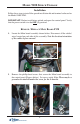
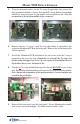
MODEL 9100 SPEECH UPGRADE Installation Follow these steps to install the speech installation kit and terminal software for the Model 9100 ATM: IMPORTANT: Before installation, unlock and open the control panel. Verify that the power switch is in the OFF (0) position! REMOVE / REPLACE MAIN BOARD PCB 1. Locate the Main board assembly shown below. Disconnect all the cables/ wires located on each side of this assembly. Note the location/orientation of the cables before removal. 2.
MODEL 9100 SPEECH UPGRADE 3. Remove the Main board assembly from the control panel and place on a flat surface. Remove the top and bottom screws from the Main board assembly using either a flat-tip screwdriver or 1/4" nut driver. Set screws aside. 4. The following steps involve separating the Main board housing. The housing for the Main board is actually two (2) panels that fit together. A. Place the Main board assembly on one end.
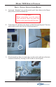
MODEL 9100 SPEECH UPGRADE 5. Using the diagonal cutters, cut the Ty-wrap (if applicable) that secures the dial-up modem module as shown. Discard the Ty-wrap. Remove the modem module by unseating from its pin holders and set modem aside. Note the orientation of the modem module before removal! 6. Remove the two (2) screws (and Ty-wrap clip holder, if applicable) that secure the Mainboard PCB to the back panel. Remove the circuit board (this will be replaced). 7.
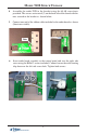
MODEL 9100 SPEECH UPGRADE DRILL / INSTALL SPEECH AUDIO BOARD 1. Locate the “dimpled” area on the control panel front shown in the Figure below. This area will be drilled out. ** CAUTION ** Before proceeding, open the control panel and check /move any cables that may be in the path of the drill location. 2. Center the 5/16" drill bit in this dimple and drill through the panel. You may want to drill a pilot hole first for centering purposes. 3.
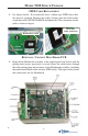
MODEL 9100 SPEECH UPGRADE 4. Assemble the audio PCB to the bracket using the #4-40 screws/nuts provided. The screws are inserted (2) on the back side of the board with the nuts secured to the bracket as shown below. 5. Connect one end of the ribbon cable included to the audio board as shown (blue tracer visible). Nuts 6. Insert audio board assembly to the control panel and start the right side screw using the K40x12 screws included.
MODEL 9100 SPEECH UPGRADE SPED CABLE REPLACEMENT 1. See figures below. If you currently have a ribbon-type SPED data cable, this must be replaced. Remove this cable. Connect one end of the multistrand data cable (P/N 09120-00630) included in kit. The connection for this cable is shown in figure. New data cable connector Ribbon data cable REINSTALL / CONNECT MAIN BOARD PCB 1. Reinstall the Mainboard assembly to the control panel and secure with the phillips-head screws previously set aside.
MODEL 9100 SPEECH UPGRADE SOFTWARE DOWNLOAD The terminal software must be loaded using the TriComm for Windows® executable program included on the Software CD (P/N 05200-00399). The following procedures describe accessing the terminal Eprom Diagnostic screen and running the TriComm for Windows program. * IMPORTANT * The EPROM chip and all associated hardware required must be installed and the EPROM must be erased prior to downloading the operating software included in the kit.
MODEL 9100 SPEECH UPGRADE ** WARNING ** This selection will erase part of the unit’s memory and should be used only with caution! Enter the erase code to proceed or cancel to end. 4. Enter the Erase Program code of 2455. When the erase operation is completed the main menu will appear. 5. Press the ERASE EEPROM option. A warning screen is displayed, as in step 3. 6. Enter the Erase EEPROM code of 2455. When the erase operation is completed the main menu will appear. 7.
MODEL 9100 SPEECH UPGRADE 2. Unlock and open the control panel of the terminal. Connect the other end of the download cable to the load port located on the Mainboard assembly shown below. Load Port CONFIGURE TRICOMM FOR WINDOWS PROGRAM 1. Insert the Software CD load disk into the CD drive of the PC. 2. Access the Windows Start\Programs menu and select the TriComm option. Select the WTriComm.exe. file. The program will start. The program’s main window will be displayed: 3. Click the Settings button.
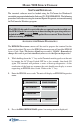
MODEL 9100 SPEECH UPGRADE 4. Choose a Com Port setting that matches the port on the PC. Click the down arrow on the Com Port control to see additional selections, as shown here: 5. Use the Drive List control to select the CD drive, which should contain the Software CD load disk.
MODEL 9100 SPEECH UPGRADE 6. Once the drive is selected, the Directory List box will show what directories are present on the disk. In most cases, additional directories below the root directory (i.e. d:\) will be present, as shown here: 7. The File List box will show the contents of the currently selected directory on the drive. Here is an example: 8.
MODEL 9100 SPEECH UPGRADE Start Software Download 1. Click the Load button on the TriComm main window. The software loading process begins. The Percent Completed progress bar will indicate the degree of completion of the file transfer. A corresponding progress indicator will appear on the terminal display during the file transfer, along with the words, “TRANSFER INITIATED.” 2.
MODEL 9100 SPEECH UPGRADE THIS PAGE INTENTIONALLY LEFT BLANK 16