TDM TO MINIMECH CONVERSION PROCEDURE (MODEL 9100 ATM) TDN 07102-00079 March 12, 2014 CORPORATE HEADQUARTERS: 21405 B Street Long Beach, MS 39560 PHONE: (800) 259-6672 FAX: (228) 868-9445 COPYRIGHT NOTICE © 2014 Triton. All Rights Reserved. TRITON logo is a registered trademark of Triton Systems of Delaware LLC.
TDM TO MINIMECH CONVERSION PROCEDURES Document Updates Apr 1, 2009 March 12, 2014 Original Part number corrections 2
TDM TO MINIMECH CONVERSION PROCEDURES PURPOSE This guide covers the steps for swapping your TDM dispenser in the Model 9100 ATM with a MiniMech dispenser. This procedure includes a list of all tools and hardware necessary for the conversion as well as the steps involved. It includes the replacement of the original power supply with an updated version. SCOPE This procedure applies to all service personnel involved in the process of maintaining or converting Triton ATMs.
TDM TO MINIMECH CONVERSION PROCEDURES REQUIRED PARTS AND TOOLS TOOLS REQUIRED #1 & #2 Phillips Screwdrivers, 1/4 & 11/32 inch nut drivers, miniature flat tip screwdriver MODEL 9100 TDM to MiniMech CONVERSION KIT P/N 06100-08134 PARTS SUPPLIED PART NUMBER DESCRIPTION QUANTITY 09120-07054 Mini-Mech Power Cable 1 09120-00073 Cable|DC|Power Supply to Docking Board 1 09120-07095 AC Power Extension Cable 1 09110-01214 Power Supply|SubAssy 1 03011-05216 Power adaptor bracket 1 02054-00302 Screw
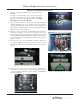
TDM TO MINIMECH CONVERSION PROCEDURES REMOVE THE TDM-100 DISPENSER Before proceeding, follow these steps to remove power from the ATM: Perform a controlled shut down as per the appropriate procedures. Then unlock and open the ATM control panel. Turn the power switch to the OFF (0) position, and unplug the ATM power cord at the wall outlet. 1. 2. 3. Open the cabinet vault door. Rotate the dispensing mechanism mounting platform to the service position.
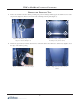
TDM TO MINIMECH CONVERSION PROCEDURES REMOVE 1. THE DISPENSER TRAY Remove the nut that secures the cabinet grounding strap to the mounting bolt that supports the left-front corner of the dispenser tray (Figure 6). Remove the nuts from the remaining mounting bolts (Figure 7). Figure 6. Grounding strap secured to dispenser tray mounting bolt. 2. Figure 7. Location of dispenser tray mounting bolts. (from bottom) Lift the tray up and away from the bolts and remove it from the cabinet.
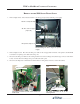
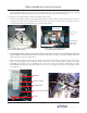
TDM TO MINIMECH CONVERSION PROCEDURES REMOVAL OF THE 9100 SINGLE POWER SUPPLY 1. Refer to Figure below. Disconnect the AC line cord and topper (if present) at the DC power supply. AC line cord (from wall) AC line cord for Topper (if present) DC power to dispenser Disconnecting the 9100 single DC power supply 2. Refer to Figures below. Disconnect the DC power cable for the receipt printer from CN1 on the printer controller PCB. Connect the new printer power cable at the same point. 3.
TDM TO MINIMECH CONVERSION PROCEDURES 5. Refer to the Figures below. Remove the DC power supply mounting screw (and ground straps if present) along the front edge of the power supply case. 6. Slide the DC power supply forward until it stops and then carefully lift it straight up from the top cabinet enclosure (with attached cables).
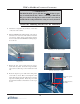
TDM TO MINIMECH CONVERSION PROCEDURES 4. Refer to the Figures below. Set the adaptor bracket with the power supply in the back of the top enclosure with the base plate (the plate side with the openings) down and the angle sides facing forward. Make sure the four (4) L-shaped locking tabs underneath the base plate slip into the four (4) open slots on the base of the top cabinet enclosure. 5. Push the power adaptor bracket towards the rear until it locks into place. 6.
TDM TO MINIMECH CONVERSION PROCEDURES *** IMPORTANT*** The Mini-Mech DC power cable has an in-line 4A fuse (a spare fuse is included in the kit). Before connecting a Mini-Mech DC power cable to the dispenser, make sure the correct fuse is installed in the casing and the fuse casing is securely fastened. Install the Mounting Bracket for the MiniMech 1. Start but do not tighten four (4) nuts (2 on each side) on the sides of the cabinet. 2.
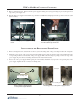
TDM TO MINIMECH CONVERSION PROCEDURES Install the Mounting Bracket and EJ 1. Place the EJ and mounting bracket as shown in the figure. Slide the EJ into the bracket. 2. Mount the EJ and mounting bracket under the right side of the dispenser bracket as shown. Secure with two (2) nuts. The EJ connectors are positioned at the top. Mounting Screws Docking board connector is on the left. Dispenser connector is on the right. 3.
TDM TO MINIMECH CONVERSION PROCEDURES Install the MiniMech Dispenser 1. EJ cable (connector may vary) Place the MiniMech on the floor in front of the ATM, facedown, printed circuit board up. Jumper Mini-Mech power cable 2. Connect the power cable and the EJ cable to the dispenser, secure the EJ cable. Ensure the jumper located between the power cable and the EJ cable remains connected. 3. Place the dispenser on the mounting tray. Slide the dispenser back until it engages the finger mounts in the rear.
TDM TO MINIMECH CONVERSION PROCEDURES Updating Terminal Software Terminal software may need to be upgraded to recognize the MiniMech and new Electronic Journal. Refer to document 07103-00014 V3 dated 12/04, Model 9100 Automated Teller Machine Service Manual, Section 8 for update instructions if necessary. Also read Section 10 on Journal entries as they pertain to the external EJ. Servicing the MiniMech Cassette The management and diagnostic functions of the ATM remain the same. All screens are the same.
REPLENISH MINI MECH CASSETTE STEP ACTION 1 UNLOCK/OPEN DISPENSER SECURITY DOOR. GRASP TRAY HANDLE AND REMOVE NOTE CASSETTE ACTION STEP 2 REMOVE 5 PLACE CURRENCY IN THE CASSETTE. 6 GRASP THE HANDLE AND SLIDE THE NOTE CASSETTE PACKER FORWARDS AGAINST THE NOTES. SLOWLY PUSH ANY REJECTED NOTES FROM THE REJECT COMPARTMENT. DO NOT RECYCLE REJECTED NOTES! 3 MOVE THE PUSHER PLATE TO THE REAR OF THE TRAY (TOWARDS THE HANDLE). 4 COUNT THE NUMBER OF BILLS THAT REMAIN IN THE CASSETTE, IF ANY.