
Owner Manual


79
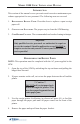
GENERAL MAINTENANCE
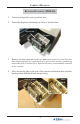
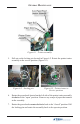
5. Pull out on the locking pin located in Figure 6-2. Rotate the printer/cutter
assembly to the service position (Figure 6-3).
Figure 6-1. Printer assembly.
Figure 6-2. Locking pin.
Figure 6-3. Printer/cutter in
Service position.
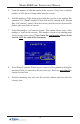
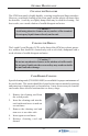
6. Rotate the green knob located on the left side of the printer/cutter assembly
clockwise to the “open” position.. Remove any scraps of paper that remain
in the assembly.
7. Rotate the green knob counterclockwise back to the “closed” position. Pull
the locking pin and rotate the assembly back to the operate position.