
Installation Instructions


Mounting and Aligning an IFU
© 2001 Triton Network Systems, Inc. All Rights Reserved. 4-11
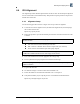
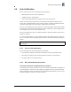
Figure 4-9: Example of An Antenna Pattern
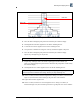
3. Move the IFU to the highest peak position as indicated by the voltmeter display.
4. Hand-tighten the horizontal alignment nut on the IFU mounting bracket.
5. Loosen the four vertical alignment screws on the mounting bracket.
6. Sweep the IFU a minimum of 10 degrees vertically and note the highest of the peaks.
7. Move the IFU to the highest peak position as indicated by the voltmeter display.
Repeat Step 1 through Step 7 for the far IFU.
8. Repeat Steps 1 through 7 until a succession of peaks appear on the voltmeter (see
Figure 4-9). Note the highest of peaks and move the IFU to the peak position as indicated by
the voltmeter display.
9. Hand-tighten the four vertical alignment screws on the IFU mounting bracket.
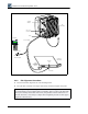
10. On the near IFU, loosen the horizontal alignment nut. Using a screwdriver, as illustrated in
Figure 4-10, move the IFU side-to-side to get the peak value on the voltmeter.
11. Tighten the horizontal alignment nut.
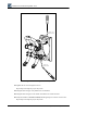
12. On the near IFU, loosen the four vertical alignment screws. Using a screwdriver, as
illustrated in Figure 4-10, move the IFU up and down to get the peak value on the voltmeter.
NOTE: If no peaks appear on the voltmeter, refer to Section 4.6, Alignment Troubleshooting.
NOTE: Alignment is an iterative process. After performing Step 1 through Step 9, Triton
Network Systems recommends “fine tuning” the link (see Steps 10 through 13).
Main Lobe
Side Lobe