
Installation Instructions

Installation and Commissioning Guide - R2.0
2-4 © 2001 Triton Network Systems, Inc. All Rights Reserved.
3. Double click on the CD-ROM drive associated with the computer.
4. Double click on folder v x-x-x (where x-x-x is the most current software version number). A
list of files opens.
5. Double click on the file named dInstall.bat.
6. As the software is being installed, an MS-DOS window appears.
7. Wait for the MS-DOS window to say Finished-dInstall on the top of the screen and then
close the MS-DOS window.
8. On your desktop, click the Start button. Select Programs
½
Windows Explorer.
9. In Windows Explorer, select the C: drive and double click on the Program Files folder.
10. Double click on the Triton folder. A list of all the files within the folder appears.
11. Right click on the file named lmngrv x-x-x.bat. A dialogue box appears.
12. In the dialogue box, click on Create Shortcut. A file named Shortcut to lmngrvx-x-x.bat
appears.
13. Click and drag the newly created file onto the desktop and then close Windows Explorer.
14. On your desktop, right click on the existing Shortcut to lmngrvx-x-x.bat icon. A dialogue
box appears.
15. Click on Properties, then the Program tab, and then the Change Icon button. The Change
Icon window appears.
16. In the Change Icon window, under File name, type in C:\Program Files\Triton\
TritonHorn.ico and click OK. The Triton Network Systems icon appears in the Change
Icon dialogue box.
17. Click OK and OK again. The Triton Horn icon appears on your desktop.
2.2.3 Connecting the IFU to the PC and Power Source
Perform the following steps to ensure the IFU is powered up and connected to your PC:
1. Connect the IFU power cable to the -48 Vdc power supply, then connect the IFU power
cable to the power connector located on the rear of the IFU.
2. Using the voltmeter, perform the cable continuity test provided in Section 5.2, IFU Power
Cable Test Procedure (Fast Ethernet applications) or Section 6.2, IFU Power Cable Test
Procedure (SONET/SDH applications). This ensures that the IFU power cable is delivering
proper voltage to the IFU.
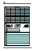
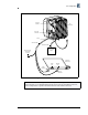
3. Connect the laptop computer to the IFU using the RJ-45 and the DB-9 connectors of the IFU
test cable assembly (see Figure 2-1).
NOTE: Ensure that the -48 Vdc power supply is turned off prior to connecting the IFU
power cable.