
Installation Instructions

Installation and Commissioning Guide - R2.0
4-8 © 2001 Triton Network Systems, Inc. All Rights Reserved.
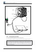
4.3.3 Attaching IFU Cables
1. Remove the dust caps from the power, GPI (optional), and fiber optic cables.
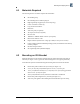
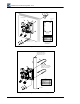
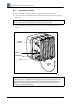
2. Connect the power, GPI (optional), and fiber optic cables to the IFU locations as shown in
Figure 4-7.
3. Secure the power, GPI (optional), and fiber optic cables to the building with tie-wraps as
needed.
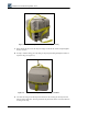
Figure 4-7: IFU Cable Connections (IFU Alignment)
NOTE: To prevent shearing of the fiber, hold the base of the fiber cable with one hand and
secure it on the connector by rotating the twist lock with your other hand.
NOTE: The connector arrangement for the IFU you are installing can be different from that
shown in Figure 4-7. To distinguish between the power connector and GPI/Test connector,
look for the protective cap that is attached to the base of the GPI/Test connector (refer to
Appendix A, Specifications for Triton Network Systems Products for Generation I and
Generation II product specifications).
Transmit
Indicator
Optical Fiber
Power
GPI/Test
Building
Ground
Cable