
Installation Instructions

Mounting and Aligning an IFU
© 2001 Triton Network Systems, Inc. All Rights Reserved. 4-3
4.1 Materials Required
The following items are needed to complete IFU installation:
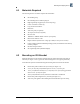
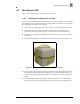
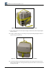
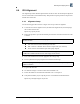
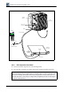
4.2 Mounting an IFU Bracket
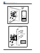
Mount the IFU bracket in the location specified in the site engineering folder using bolts as
indicated (see Figure 4-1 for a typical wall mount and Figure 4-2 for a typical pole mount).
Triton Network Systems recommends using the following items to install an IFU bracket:
o
IFU handling strap
o
IFU mounting bracket with snap ring kit
o
Right-angled snap ring pliers (for external snap ring)
o
9/16 in. wrenches or sockets (2)
o
Large flat head screwdriver
o
Binoculars
o
Anti-seize paste (as required)
o
Tie-wraps, UV-rated (as required)
o
IFU test cable
o
10BaseFL to 10BaseT Media Converter (as required)
o
BNC-banana interface cable
o
Digital voltmeter (measures DC voltage up to 100V, accuracy 0.3% or better)
o
Laptop computer, Windows 98/2000 operating system, and an Ethernet card with any
necessary adapters
o
IFU link manager software
o
Site engineering folder (with link budgets)
o
Bracket hole pattern width 4.5 in.s (114.3 mm) (see Figure 4-1)
o
4.5 in. (11 cm) O.D. pole (minimum pole size is 3 in. (7 cm) O.D. pole
o
1/2 in. (1 cm) diameter U-Bolt, 4.5” (11 cm) wide, 6.5 in. (16 cm) long galvanized
steel for 4.5 in. (11 cm) O.D. poles
o
3/8 in. (9 mm) diameter U-bolt, stainless steel SAE GR5 or ASTM 325
o
Bracket hole pattern length 10.9 in. (276 mm) (see Figure 4-1)
o
Anti-seize paste applied to the mounting bracket bolt threads to prevent seizing