
Installation Instructions

Cable Installation
© 2001 Triton Network Systems, Inc. All Rights Reserved. 3-5
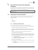
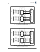
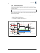
Figure 3-1: Typical IFU Power Termination Wiring Diagram
(single wire pair in building for each IFU)
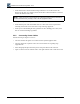
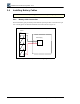
Figure 3-2: Typical IFU Power Termination Wiring Diagram
(dual wire pair in building for each IFU)
WH - 1
IFU Alpha
Power
Cable
PIN A
PIN B
PIN C
PIN D
PIN A
PIN B
PIN C
PIN D
WH/RD - 2
Surge
Suppressor
Surge
Suppressor
GND
IFU Beta
Power
Cable
Power
Supply
IFU Alpha
Return
Surge
++
--
- 48 Vdc
RTN
Protected
GND
Surge
++
--
- 48 Vdc
RTN
Protected
To IFU
Demarcation
Location (Optional)
Site Equipment
IFU Beta
Return
IFU Alpha
-48 Vdc
IFU Beta
-48 Vdc
WH/BN - 3
WH/BK -4
WH - 2A
WH/RD - 2B
WH/BN -2C
WH/BK - 2D
Shield
Shield
Shield
Shield
Shield
Shield
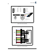
WH - 1
IFU Alpha
Power
Cable
PIN A
PIN B
PIN C
PIN D
PIN A
PIN B
PIN C
PIN D
WH/RD - 2
Surge
Suppressor
Surge
Suppressor
GND
IFU Beta
Power
Cable
Power
Supply
IFU Alpha
Return
Surge
++
--
- 48 Vdc
RTN
Protected
GND
Surge
++
--
- 48 Vdc
RTN
Protected
To IFU
Demarcation
Site Equipment
IFU Beta
Return
IFU Alpha
-48 Vdc
IFU Beta
-48 Vdc
1
2
3
4
8
7
6
5
WH/BN - 3
WH/BK -4
WH - 2A
WH/RD - 2B
WH/BN -2C
WH/BK - 2D
Shield
Shield
Shield
Shield
Shield
Shield