
Installation Manual
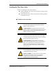
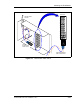
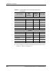
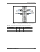
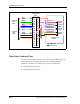
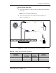
Table Of Contents
- List of Figures
- List of Tables
- About This Book
- Warnings and Safety Guidelines
- Avertissements et consignes de sécurité
- Conventions
- Risque de lésions corporelles provoquées par la décharge électrique
- Risque de lésions corporelles provoquées par les câbles à fibres optiques
- Risque de lésions corporelles provoquées par l’exposition de l’énergie radiofréquences
- Autres risques des lésions corporelles
- Risque d’interruption de service
- Autres mises en garde
- Installation Overview
- Staging Procedure
- Installation Procedures
- Alignment Procedures
- Removing an IFU
- IFU Test Results
- Invisible Fiber™ Product Glossary
- Index

Installation Procedures
3-22 © 1999 Triton Network Systems, Inc. All Rights Reserved.
3 Connect the optical light source to the IFU Alpha test adapter as called
out in Table 3-6.
4 Set the optical light source to 0 dBm continuous wave and 1310 nm.
5 Turn on the optical power meter and optical light source and take readings
at the power meter. Record the results in Table A-2 on page A-2.
NOTE: The received signal should be stronger than – 5.0 dBm (less
than 5.0 dBm).
Repeat Steps 1 through 5 on each fiber optic cable.
Installing an IFU
IFUs are installed in the locations specified by each site drawing. A near-end
IFU is the first installed IFU in a pair, and the far-end IFU is the second in the
pair. Figure 3-10 provides a close-up view of an installed IFU. Installing an
IFU is a two-part process that consists of the following:
1 Mounting the IFU to the mounting bracket
2 Attaching cables to the IFU