
Installation Manual
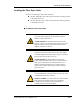
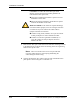
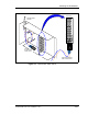
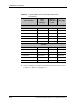
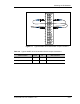
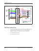
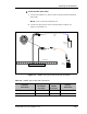
Table Of Contents
- List of Figures
- List of Tables
- About This Book
- Warnings and Safety Guidelines
- Avertissements et consignes de sécurité
- Conventions
- Risque de lésions corporelles provoquées par la décharge électrique
- Risque de lésions corporelles provoquées par les câbles à fibres optiques
- Risque de lésions corporelles provoquées par l’exposition de l’énergie radiofréquences
- Autres risques des lésions corporelles
- Risque d’interruption de service
- Autres mises en garde
- Installation Overview
- Staging Procedure
- Installation Procedures
- Alignment Procedures
- Removing an IFU
- IFU Test Results
- Invisible Fiber™ Product Glossary
- Index

Mounting the IFU Bracket
28 GHz SONET OC-3 IFU Installation - R1.0 3-21
To test the fiber optic cable:
1 Connect the SONET OC-3 FSI test cable to the IFU Alpha and IFU Beta
fiber cables.
NOTE: Never connect the transmitter first.
2 Connect the optical power meter to the IFU Beta test adapter (see
Figure 3-9 and Table 3-6).
Figure 3-9. SONET OC-3 Fiber Optic Continuity Test Setup
Outside Building
INSIDE BUILDING
Optical
Light Source
Demarcation Box
IFU Alpha
Fiber Cable
IFU Beta
Fiber Cable
Optical
Power Meter
Plug
Connection
12
43
65
7
8
FSI Test
Cable
FSI Test
Cable
Table 3-6. SONET OC-3 Fiber Test Connections
IFU Alpha
Fiber Name
IFU Alpha
Test Adapter
Connector
IFU Beta Test
Adapter
Connector
IFU Beta
Fiber Name
IFU Alpha Interconnect TX 7 8 IFU Beta Interconnect RX
IFU Alpha Interconnect RX 8 7 IFU Beta Interconnect TX