
Installation Manual
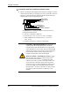
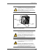
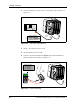
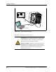
Table Of Contents
- List of Figures
- List of Tables
- About This Book
- Warnings and Safety Guidelines
- Avertissements et consignes de sécurité
- Conventions
- Risque de lésions corporelles provoquées par la décharge électrique
- Risque de lésions corporelles provoquées par les câbles à fibres optiques
- Risque de lésions corporelles provoquées par l’exposition de l’énergie radiofréquences
- Autres risques des lésions corporelles
- Risque d’interruption de service
- Autres mises en garde
- Installation Overview
- Staging Procedure
- Installation Procedures
- Alignment Procedures
- Removing an IFU
- IFU Test Results
- Invisible Fiber™ Product Glossary
- Index

Configuring IFUs
28 GHz SONET OC-3 IFU Installation - R1.0 2-5
6 Connect a red test lead from the positive input of the multimeter to pin D
on the IFU power cable.
7 Read the measurement on the multimeter. Passing criteria is – 46 Vdc to
– 56 Vdc.
8 Connect a black test lead from the negative input of the multimeter to
pin A on the IFU power cable.
9 Connect a red test lead from the positive input of the multimeter to pin C
on the IFU power cable.
10 Read the measurement on the multimeter. Passing criteria is – 46 Vdc to
– 56 Vdc.
11 Set the – 48 Vdc power source to OFF.
12 Connect the – 48 Vdc power cable to the power connector on the IFU as
illustrated in Figure 2-4.
DANGER – HIGH CURRENT HAZARD: Do not turn
on power before reading the Triton Network Systems’
product documentation. This device has a – 48 Vdc
(5 amps operating peak per feed) direct current input.
DANGER – L’HASARD DU COURANT ÉLEVÉ : Ne
pas mettre la tension avant de lire la documentation du
produit fournie par la société Triton Network Systems. Cet
appareil a une alimentation directe de – 48 V CC (courant
de pointe de 5 ampères par ligne d’alimentation).
DANGER – HIGH CURRENT HAZARD: Ensure that
the – 48 Vdc power source is set to the OFF position
before beginning the installation procedures for the
Invisible Fiber™ Unit.
DANGER – L’HASARD DU COURANT ÉLEVÉ :
S’assurer que le bloc d’alimentation – 48 V CC est en
position HORS TENSION avant d’aborder les procédures
pour l’installation de l’unité Invisible Fiber
MD
.