
Installation Manual
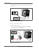
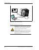
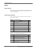
Table Of Contents
- List of Figures
- List of Tables
- About This Book
- Warnings and Safety Guidelines
- Avertissements et consignes de sécurité
- Conventions
- Risque de lésions corporelles provoquées par la décharge électrique
- Risque de lésions corporelles provoquées par les câbles à fibres optiques
- Risque de lésions corporelles provoquées par l’exposition de l’énergie radiofréquences
- Autres risques des lésions corporelles
- Risque d’interruption de service
- Autres mises en garde
- Installation Overview
- Staging Procedure
- Installation Procedures
- Alignment Procedures
- Removing an IFU
- IFU Test Results
- Invisible Fiber™ Product Glossary
- Index

28 GHz SONET OC-3 IFU Installation - R1.0 2-1
2
Staging Procedure
This chapter describes the IFU configuration procedure to be performed at the
designated staging area.
Configuring IFUs
IFUs are configured by using the IFU Link Manager application to load the
site-specific attributes from the attributes table in the site engineering folder.
Table 2-1 identifies the parts needed for configuring a typical IFU site.
Figure 2-1 refers to the IFU and the IFU lifting guidelines.
Table 2-1. Typical IFU Configuration Parts List
Item
No.
Description Qty.
1IFU 1
2 BNC-banana plug adapter 1
3 IFU Link Manager test cable 1
4 Laptop computer with IFU Link Manager installed 1
5 Power source (– 48 Vdc) 1
6 IFU power cable 1
7 Site engineering folder 1
8 Digital multimeter 1