
Installation Manual
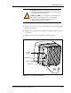
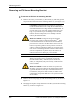
Table Of Contents
- Contents
- List of Figures
- List of Tables
- About This Book
- Warnings and Safety Guidelines
- Avertissements et consignes de sécurité
- Conventions
- Risque de lésions corporelles provoquées par la décharge électrique
- Risque de lésions corporelles provoquées par les câbles à fibres optiques
- Risque de lésions corporelles provoquées par l’exposition de l’énergie radiofréquences
- Autres risques des lésions corporelles
- Risque d’interruption de service
- Autres mises en garde
- Installation Overview
- Staging Procedure
- Installation Procedures
- Alignment Procedures
- Removing an IFU
- IFU Test Results
- Invisible Fiber™ Product Glossary
- Index

Alignment Procedures
4-8 © 1999 Triton Network Systems, Inc. All Rights Reserved.
3 While viewing the multimeter, sweep the IFU vertically by pointing the
IFU all the way up and then down. The measured voltage of the
multimeter displays a succession of peak signals as the IFU moves.
Specifically, the signal displays a “small” peak, a relatively higher peak,
and then redisplays the “small” peak. When the higher peak occurs, note
the approximate position of the IFU and the corresponding voltage value.
The peak voltage should be approximately 3 Vdc.
4 Move the IFU to the higher peak position as indicated by the multimeter
display.
5 Tighten the four vertical screws on the IFU mounting bracket.
6 Loosen the horizontal alignment nut on the IFU mounting bracket.
7 Sweep the IFU from the far left to the far right. The measured voltage of
the multimeter displays a succession of peak signals as the IFU moves.
When the higher peak occurs, note the approximate position of the IFU
and the corresponding voltage value.
8 Move the IFU to the higher peak position as indicated by the multimeter
display.
9 Tighten the horizontal alignment nut on the IFU mounting bracket.