
Installation Manual
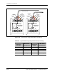
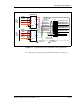

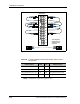
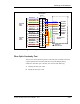
Table Of Contents
- Contents
- List of Figures
- List of Tables
- About This Book
- Warnings and Safety Guidelines
- Avertissements et consignes de sécurité
- Conventions
- Risque de lésions corporelles provoquées par la décharge électrique
- Risque de lésions corporelles provoquées par les câbles à fibres optiques
- Risque de lésions corporelles provoquées par l’exposition de l’énergie radiofréquences
- Autres risques des lésions corporelles
- Risque d’interruption de service
- Autres mises en garde
- Installation Overview
- Staging Procedure
- Installation Procedures
- Alignment Procedures
- Removing an IFU
- IFU Test Results
- Invisible Fiber™ Product Glossary
- Index

Mounting the IFU Bracket
28 GHz 100 Mbps Internet IFU Installation - R1.0 3-21
Figure 3-10. Typical 100 Mbps Internet Site Schematic
Fiber Optic Continuity Test
This test is to ensure that the signal loss in the fiber optic assemblies meets the
required specifications and that cables have not been damaged during
installation. The fiber optic continuity test consists of the following:
1 Cleaning the fiber optic cable
2 Testing the fiber optic cable
Demarcation
Panel
IFU Alpha
Fiber
Cable
Blue (FA-1)
Orange (FA-2)
Green (FA-3)
1
2
3
4
Brown (FA-4)
Slate (FA-5)
White (FA-6)
Red (FA-7)
5
6
7
8
Black (FA-8)
1A
1B
2A
2B
3A
3B
4A
4B
Rear
Front
1A
1B
2A
2B
3A
3B
4A
4B
IFU Beta
Fiber
Cable
1
2
3
4
5
6
7
8
5A
5B
6A
6B
7A
7B
8A
8B
5A
5B
6A
6B
7A
7B
8A
8B
1
3
2
4
IFU Alpha
Add/Drop
IFU Alpha
OAM&P
IFU Beta
Add/Drop
IFU Beta
OAM&P
Site Equipment
Cabinet
TX
RX
TX
RX
TX
RX
TX
RX
TX
RX
TX
RX
TX
RX
TX
RX
Chassis to
Earth Ground
Blue (FB-1)
Orange (FB-2)
Green (FB-3)
Brown (FB-4)
Slate (FB-5)
White (FB-6)
Red (FB-7)
Black (FB-8)
Blue (FA-3)
Orange (FA-4)
Green (FB-3)
Brown (FB-4)
Slate (FA-5)
White (FA-6)
Red (FB-5)
Black (FB-6)