
Installation Manual
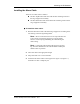
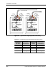
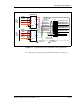

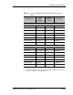
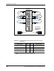
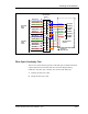
Table Of Contents
- Contents
- List of Figures
- List of Tables
- About This Book
- Warnings and Safety Guidelines
- Avertissements et consignes de sécurité
- Conventions
- Risque de lésions corporelles provoquées par la décharge électrique
- Risque de lésions corporelles provoquées par les câbles à fibres optiques
- Risque de lésions corporelles provoquées par l’exposition de l’énergie radiofréquences
- Autres risques des lésions corporelles
- Risque d’interruption de service
- Autres mises en garde
- Installation Overview
- Staging Procedure
- Installation Procedures
- Alignment Procedures
- Removing an IFU
- IFU Test Results
- Invisible Fiber™ Product Glossary
- Index

Installation Procedures
3-14 © 1999 Triton Network Systems, Inc. All Rights Reserved.
Figure 3-6. Typical Alarm Surge Suppressor Panel Wiring
IFU Beta
Alarm Surge
Supperssor
1
1
1
1
2
2
2
2
3
3
3
3
4
4
4
4
IFU Beta Alarm Cable
White/Orange
(P1-36)
IFU Alpha Alarm Cable
White/Black
(P1-31)
White/Brown
(P1-33)
White/Red
(P1-34)
Shield
Lines
Equipment
Lines
Equipment
IFU Alpha
Alarm Surge
Supperssor
White/Black
(P2-31)
White/Brown
(P2-33)
Shield
White/Red
(P2-34)
White/Orange
(P2-36)
Table 3-4. Typical Alarm Surge Suppressor Panel Input Wiring
Alarm
Suppressor
IFU Alpha
Wire Color/
Connector Pin
Alarm
Suppressor
IFU Beta
Wire Color/
Connector Pin
1 (line) White/Black (31) 1 (line) White/Black (31)
2 (line) White/Brown (33) 2 (line) White/Brown (33)
3 (line) White/Red (34) 3 (line) White/Red (34)
4 (line) White/Orange (36) 4 (line) White/Orange (36)