
Installation Manual
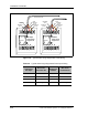
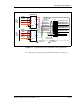

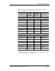
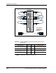
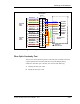
Table Of Contents
- Contents
- List of Figures
- List of Tables
- About This Book
- Warnings and Safety Guidelines
- Avertissements et consignes de sécurité
- Conventions
- Risque de lésions corporelles provoquées par la décharge électrique
- Risque de lésions corporelles provoquées par les câbles à fibres optiques
- Risque de lésions corporelles provoquées par l’exposition de l’énergie radiofréquences
- Autres risques des lésions corporelles
- Risque d’interruption de service
- Autres mises en garde
- Installation Overview
- Staging Procedure
- Installation Procedures
- Alignment Procedures
- Removing an IFU
- IFU Test Results
- Invisible Fiber™ Product Glossary
- Index

Mounting the IFU Bracket
28 GHz 100 Mbps Internet IFU Installation - R1.0 3-13
Installing the Alarm Cable
There are two cable routes as follows:
The IFU Alpha alarm cable runs from the IFU mounting location to
the surge suppression assembly.
The IFU Beta alarm cable runs from the IFU mounting location to the
surge suppression assembly.
To install the alarm cable:
1 Route the IFU alarm cable to the alarm surge suppressors according to the
site drawing in the site engineering folder.
NOTE: Allow an extra three-foot service loop at the IFU and
twelve inches at each surge suppressor. Use large radius
bends to avoid crimping and kinking the cables during the
cable routing.
NOTE: Connect the cable shield to the suppressor ground
lug. Trim the shield back to the cable breakout and keep the
shield as short as possible.
2 Trim each cable to the appropriate length.
3 Strip each cable wire to 3/8 inch and tin.
4 Attach the IFU alarm cables to the suppressors. Figure 3-6, Figure 3-7,
and Table 3-4 show a sample layout.