
Installation Manual
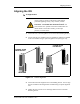
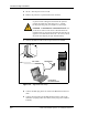
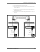

Table Of Contents
- Contents
- List of Figures
- List of Tables
- About This Book
- Warnings and Safety Guidelines
- Avertissements et consignes de sécurité
- Conventions
- Risque de lésions corporelles provoquées par la décharge électrique
- Risque de lésions corporelles provoquées par les câbles à fibres optiques
- Risque de lésions corporelles provoquées par l’exposition de l’énergie radiofréquences
- Autres risques des lésions corporelles
- Risque d’interruption de service
- Autres mises en garde
- Installation Overview
- Staging Procedure
- Installation Procedures
- Commissioning Procedures
- Removing an IFU
- IFU Test Results

Commissioning Procedures
4-8 © 1999 Triton Network Systems, Inc. All Rights Reserved.
4 Move the IFU to the higher peak position as indicated by the multimeter
display.
5 Tighten the four vertical screws on the IFU mounting bracket.
6 Loosen the horizontal alignment nut on the IFU mounting bracket.
7 Sweep the IFU from the far left to the far right. The measured voltage of
the multimeter displays a succession of peak signals as the IFU moves.
Note the approximate position of the IFU when the higher peak occurs
and the corresponding voltage value.
8 Move the IFU to the higher peak position as indicated by the multimeter
display.
9 Tighten the horizontal alignment nut on the IFU mounting bracket.
10 Access the IFU Link Manager application and enable Power Control for
both the near-end and the far-end IFUs (see IFU Link Manager online
help).
11 Record the minimum, maximum, and actual RSSI levels set for the IFU in
Table A-3 and Table A-5.
12 Turn off the laptops, disconnect the test cables, and replace the protective
caps on the IFU test connectors.
13 Secure all IFU cabling with UV-rated tie-wraps. Continue to tie wrap the
cables every 18 inches until they enter the building.
SONET OC-3 Link Performance Test
This test verifies the continuity of the optical fiber signal path end to end.
To perform the Link Performance Test:
1 Configure both SONET test sets for OC-3 testing and connect fiber patch
cables as shown in Figure 4-3.
2 Test sets will sync up with each other and run head to head. Record the
results in Table A-5.
3 Configure both SONET test sets for DS-3 testing and connect fiber patch
cables as shown in Figure 4-3.
4 Test sets will sync up with each other and run head to head. Record the
results in Table A-5.