
Installation Manual
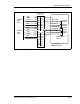
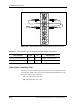
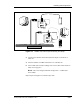
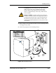
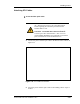
Table Of Contents
- Contents
- List of Figures
- List of Tables
- About This Book
- Warnings and Safety Guidelines
- Avertissements et consignes de sécurité
- Conventions
- Risque de lésions corporelles provoquées par la décharge électrique
- Risque de lésions corporelles provoquées par les câbles à fibres optiques
- Risque de lésions corporelles provoquées par l’exposition de l’énergie radiofréquences
- Autres risques des lésions corporelles
- Risque d’interruption de service
- Autres mises en garde
- Installation Overview
- Staging Procedure
- Installation Procedures
- Commissioning Procedures
- Removing an IFU
- IFU Test Results

Installing IFU Components
28 GHz SONET OC-3 IFU Installation - R1.0 3-17
Figure 3-9. SONET OC-3 Fiber Optic Continuity Test Setup
3 Connect the transmitter to the IFU Alpha test adapter as called out in
Table 3-6.
4 Set the transmitter to 0 dBm continuous wave and 1310 nm.
5 Turn on both units and take readings at the receiver. Record the results in
Table A-2 on page A-2.
NOTE: The received signal should be stronger than – 7.4 dBm (less
than 7.4 dB).
Repeat steps 1 through 5 on each fiber optic cable.
Outside Building
INSIDE BUILDING
Laser
Transmitter
Test
Adapter
IFU Beta
IFU Alpha
Demarcation Box
IFU Alpha
Fiber Cable
IFU Beta
Fiber Cable
Laser
Receiver
Test
Adapter
7
8
6
SONET TEST BOX
5
Multimode
Single-Mode
1
2
7
8
6
SONET TEST BOX
5
Multimode
Single-Mode
1
2