
Installation Manual
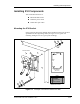
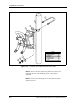
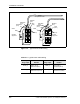
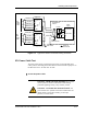
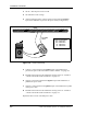
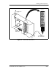
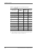
Table Of Contents
- Contents
- List of Figures
- List of Tables
- About This Book
- Warnings and Safety Guidelines
- Avertissements et consignes de sécurité
- Conventions
- Risque de lésions corporelles provoquées par la décharge électrique
- Risque de lésions corporelles provoquées par les câbles à fibres optiques
- Risque de lésions corporelles provoquées par l’exposition de l’énergie radiofréquences
- Autres risques des lésions corporelles
- Risque d’interruption de service
- Autres mises en garde
- Installation Overview
- Staging Procedure
- Installation Procedures
- Commissioning Procedures
- Removing an IFU
- IFU Test Results

Installation Procedures
3-12 © 1999 Triton Network Systems, Inc. All Rights Reserved.
3 Connect the jumpers to the front of the demarcation patch panel as shown
in Figure 3-6, Figure 3-7, Figure 3-8 and Table 3-5.
Table 3-4. Typical SONET OC-3 Demarcation Panel Input
Connections
Fiber Function
Fiber
Color/Number
Rear of
Demarcation
Panel
Fiber Type
IFU Alpha Payload TX Gray (FA-1) 1A Single-Mode
IFU Alpha Payload RX White (FA-2) 1B Single-Mode
IFU Alpha OAM&P TX Green (FA-3) 2A Multimode
IFU Alpha OAM&P RX Brown (FA-6) 2B Multimode
IFU Alpha Interconnect
TX
Blue (FA-7) 3A Multimode
IFU Alpha Interconnect
RX
Orange (FA-8) 3B Multimode
IFU Beta Payload TX Gray (FB-1) 4A Single-Mode
IFU Beta Payload RX White (FB-2) 4B Single-Mode
IFU Beta OAM&P TX Green (FB-3) 5A Multimode
IFU Beta OAM&P RX Brown (FB-6) 5B Multimode
IFU Beta Interconnect TX Blue (FB-7) 6A Multimode
IFU Beta Interconnect RX Orange (FB-8) 6B Multimode