
Installation Manual
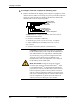
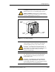
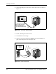
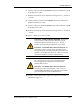
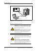

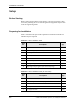
Table Of Contents
- Contents
- List of Figures
- List of Tables
- About This Book
- Warnings and Safety Guidelines
- Avertissements et consignes de sécurité
- Conventions
- Risque de lésions corporelles provoquées par la décharge électrique
- Risque de lésions corporelles provoquées par les câbles à fibres optiques
- Risque de lésions corporelles provoquées par l’exposition de l’énergie radiofréquences
- Autres risques des lésions corporelles
- Risque d’interruption de service
- Autres mises en garde
- Installation Overview
- Staging Procedure
- Installation Procedures
- Commissioning Procedures
- Removing an IFU
- IFU Test Results

Staging Procedure
2-4 © 1999 Triton Network Systems, Inc. All Rights Reserved.
2 Connect the IFU power cable to the – 48 Vdc power source as shown in
Figure 2-2.
Figure 2-2. IFU Power Cable Hookup
3 Set the – 48 Vdc power source to ON.
4 Set multimeter to DC voltage.
5 Connect a black test lead from the negative input of the multimeter to
pin C on the IFU power cable (see Figure 2-3).
Figure 2-3. Power Test Setup
34567
D
C
B
E
F
G
IFU
POWER
CABLE
- 48 VDC POWER
SOURCE
- 48
RTN
RTN WHITE/RED (CABLE PIN C)
RTN WHITE (CABLE PIN H)
- 48 WHITE/BLACK (CABLE PIN A)
- 48 WHITE/BROWN (CABLE PIN B)
CABLE WIRE COLOR CODE
34
D
C
567
E
F
D
C
B
E
F
G
TEXT
TEXT
TEXT TEXT
TEXT TEXT
TEXT TEXT
TEXT TEXT
TEXT
TEXT
- 48
+
-
MULTIMETER
IFU
RTN CABLE PIN C
RTN CABLE PIN H
- 48 CABLE PIN A
- 48 CABLE PIN B
CABLE PIN ASSIGNMENT
IFU POWER
CABLE
A
E
D
C
B
H
G
F