
Installation Manual
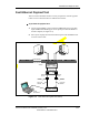
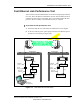


Table Of Contents
- List of Figures
- List of Tables
- About This Book
- Warnings and Safety Guidelines
- Avertissements et consignes de sécurité
- Conventions
- Risque de lésions corporelles provoquées par la décharge électrique
- Risque de lésions corporelles provoquées par les câbles à fibres optiques
- Risque de lésions corporelles provoquées par l’exposition de l’énergie radiofréquences
- Autres risques des lésions corporelles
- Risque d’interruption de service
- Autres mises en garde
- Installation Overview
- Staging Procedure
- Installation Procedures
- Commissioning Procedures
- Removing an IFU
- IFU Test Results
- Index

Commissioning Procedures
4-12 © 1999 Triton Network Systems, Inc. All Rights Reserved.
CONFIDENTIAL & PROPRIETARY
D
O
N
O
T
C
O
P
Y
3 Connect a power cable to the hub.
NOTE: When connecting the laptop, hub, and converters, make sure
the link light is illuminated on all of the devices. If the light does not
illuminate when both ends of the cable are connected, check the
connections.
4 Connect the media converter to the hub with a CAT-5 cable.
5 In the site equipment cabinet, connect a 10BaseFL cable between the hub
and the OAM&P port for the near-end IFU being tested.
6 Connect a power cable to the media converter and the SmartBits™ test set
and power up the SmartBits™ test set.
7 Connect the Ethernet port on the back of the SmartBits™ test set to the
hub input with a CAT-5 cable.
8 Connect the SmartBits™ test set Port 3 to the near-end IFU’s Add/Drop
port in the site equipment cabinet. Connect the MT-RJ to SC adapters and
the 100BaseFX fiber with the coupler from Port 3 to the IFU’s Add/Drop
port on the site equipment cabinet.
9 At the far-end site, connect a power cable to the media converter and the
SmartBits™ test set and power up the SmartBits™ test set.
10 Connect the SmartBits™ test set Port 4 to the far-end IFU Add/Drop port
in the site equipment cabinet. Connect the MT-RJ to SC adapters and the
100BaseFX fiber with the coupler from port 4 to the IFU's Add/Drop port
on the site equipment cabinet.
11 Connect the media converter to the SmartBits™ with a CAT-5 cable.
12 Connect the far-end IFU’s OAM&P port in the site equipment cabinet to
the converter with a 10BaseFL cable.
13 On the near-end laptop, select Start>Run and then type command to
open a DOS box window.
14 Type Ping XXX.XXX.XXX.XXX (XXX is the IP address of the
SmartBits™ test set) to link the SmartBits™ test sets.
15 On the laptop, open the SmartApplication™ program.
16 Select File>Open and then click IFU Link Test (file provided by Triton
Network Systems).
17 Select Run and then click Packet Errors to run the Packet Error tests.