
Installation Manual
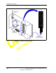
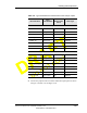
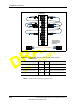
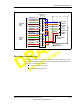
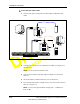
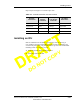
Table Of Contents
- List of Figures
- List of Tables
- About This Book
- Warnings and Safety Guidelines
- Avertissements et consignes de sécurité
- Conventions
- Risque de lésions corporelles provoquées par la décharge électrique
- Risque de lésions corporelles provoquées par les câbles à fibres optiques
- Risque de lésions corporelles provoquées par l’exposition de l’énergie radiofréquences
- Autres risques des lésions corporelles
- Risque d’interruption de service
- Autres mises en garde
- Installation Overview
- Staging Procedure
- Installation Procedures
- Commissioning Procedures
- Removing an IFU
- IFU Test Results
- Index

Installing an IFU
28 GHz Fast Ethernet IFU Installation (9/17/99) - R0.1 3-21
CONFIDENTIAL & PROPRIETARY
D
O
N
O
T
C
O
P
Y
Repeat steps 1 through 5 on each fiber optic cable.
Installing an IFU
IFUs are installed in the locations as specified by each site drawing. A
near-end IFU is the first installed IFU in a pair, and the far-end IFU is the
second in the pair. Figure 3-12 provides a close-up view of an installed IFU.
Installing an IFU is a two-part process:
1 Mounting the IFU to the mounting bracket.
2 Attaching cables to the IFU.
Table 3-7. Fast Ethernet Fiber Test Connections
IFU Beta
Fiber Name
IFU Beta Test
Adapter
Connector
IFU Alpha
Test Adapter
Connector
IFU Alpha
Fiber Name
Payload RX 2 Orange 1 Blue Payload TX
Payload TX 1 Blue 2 Orange Payload RX
Interconnect RX 8 Black 7 Red Interconnect TX
Interconnect TX 7 Red 8 Black Interconnect RX