
Installation Manual
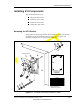
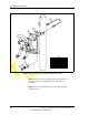
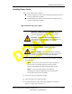
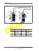
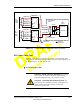
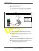
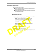
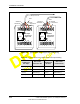
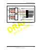
Table Of Contents
- List of Figures
- List of Tables
- About This Book
- Warnings and Safety Guidelines
- Avertissements et consignes de sécurité
- Conventions
- Risque de lésions corporelles provoquées par la décharge électrique
- Risque de lésions corporelles provoquées par les câbles à fibres optiques
- Risque de lésions corporelles provoquées par l’exposition de l’énergie radiofréquences
- Autres risques des lésions corporelles
- Risque d’interruption de service
- Autres mises en garde
- Installation Overview
- Staging Procedure
- Installation Procedures
- Commissioning Procedures
- Removing an IFU
- IFU Test Results
- Index

Installing IFU Components
28 GHz Fast Ethernet IFU Installation (9/17/99) - R0.1 3-7
CONFIDENTIAL & PROPRIETARY
D
O
N
O
T
C
O
P
Y
Figure 3-4. Typical IFU Power Termination Wiring Schematic
IFU Power Cable Test
To ensure proper wiring, perform the input power test on both IFU power
cables prior to connecting to the IFU. This test ensures that the input power to
the IFU is between – 46 Vdc and – 56 Vdc.
To test the power cable:
RTN
WH (PA-2)
A
IFU
Alpha
Power
Cable
WH/BK (PA-4)
B
- 48
Vdc
WH/BN (PA-3)
C
WH/RD (PA-1)
H
Suppressor
GND
Shield
RTN
IFU
Beta
Power
Cable
- 48
Vdc
GND
Shield
F1 Conn
+
+
-
Power
Source
F1
Common Bar
F2
Common Bar
F2 Conn
Shield to
Chassis Ground
Site Equipment
Cabinet
S
u
r
g
e
P
r
o
t
e
c
t
e
d
P
r
o
t
e
c
t
e
d
S
u
r
g
e
+
+
+
+
-
-
-
-
-
-
-
White (PB-2)
Brown (PB-3)
Black (PA-4)
Red (PA-1)
White
Red
Brown
Black
++
A
B
C
H
WH (PB-2)
WH/BK (PB-4)
WH/BN (PB-3)
WH/RD (PB-1)
Chassis to
Earth Ground
Panel to
Earth Ground
DANGER – HIGH VOLTAGE HAZARD: Do not work
on the system or connect or disconnect cables during
periods of lightning activity, rainy weather, or both.
DANGER – L’HASARD DU TENSION ÉLEVÉ : Ne
pas travailler sur le système ni brancher ni débrancher les
câbles durant l’activité de la foudre, par de temps
pluvieux, ou tous le deux.