
Installation Manual

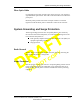
Table Of Contents
- List of Figures
- List of Tables
- About This Book
- Warnings and Safety Guidelines
- Avertissements et consignes de sécurité
- Conventions
- Risque de lésions corporelles provoquées par la décharge électrique
- Risque de lésions corporelles provoquées par les câbles à fibres optiques
- Risque de lésions corporelles provoquées par l’exposition de l’énergie radiofréquences
- Autres risques des lésions corporelles
- Risque d’interruption de service
- Autres mises en garde
- Installation Overview
- Staging Procedure
- Installation Procedures
- Commissioning Procedures
- Removing an IFU
- IFU Test Results
- Index

System Grounding and Surge Protection
28 GHz Fast Ethernet IFU Installation (9/17/99) - R0.1 1-3
CONFIDENTIAL & PROPRIETARY
D
O
N
O
T
C
O
P
Y
Fiber Optic Cable
For Fast Ethernet networks, the fiber optic cable (see Figure 1-1) consists of
eight multimode optical fibers. This cable connects the IFU to an indoor fiber
patch panel.
Breakout jackets provide strain relief. Each pair of fibers is connected
together from the breakout jacket to within three inches of the connector.
System Grounding and Surge Protection
The IFU grounding system has two conceptually distinct, but electrically
interconnected functional subsystems, for connection to “earth ground.” The
two functional subsystems are:
n
Earth ground (complies with the National Electrical Code (NEC) for
equipment grounding systems).
n
Surge protection.
Earth Ground
The IFU has an external electrical interconnection point for connecting the
IFU ground subsystems to earth ground.
Surge Protection
The sole purpose of surge protection is to transport lightning-related currents
to the earth ground. During site installation, surge suppression devices are
installed inline with the power and alarm conductors to assist in protecting
equipment.