9 TRIPPaUTE POWER PRorEcTloN N 1111 W. 35th Street Chlcago, IL 60609 USA Customer Support: (773) 869-1234 Application Services: (773) 869-1236 www.tripplite.com 1 Capyrighl 0 MOI Tripp tile. All ri@umrved. Smam3nlieN is a rcgisterrd trademark of Tripp Lite.
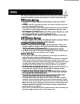
This manual contains important instructions and warnings that should be followed during the installation, operation and storage of all Tripp Lite SmartOnline UPS Systems. UPS Location Warnings Install your UPS indoors, away from excess moisture or heat, dust or direct sunlight. Install your UPS in a structurally sound area. Your UPS is extremely heavy; take care when moving and lifting the unit. Only operate your UPS at indoor temperatures between 32" F and 104" F (between 0"C and 40" C).
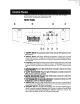
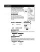
Familiarize yourself with the location and function of the front and rear panel features before installing and operating your UPS. FRONT PANEL 0 0 0 0 UPS SYSTEM , 5 1. "ON/OFFn Switch: This momentary rocker switch turns the UPS System's inverter ON and OFF. 2.
SUBP
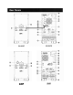
REAR PANELS 1. Manual Bypass Switch:This red and yellow dial is used in one step of putting the UPS in "BYPASS"mode, which must be done before performingany maintenance on the UPS with the connected load supported. (See page 12 for step-by-step instructions for going into "BYPASS.")While this switch is on "BYPASS." connected equipment will receive filtered AC mains power, but will not receive battery power in the event of a blackout. 2.
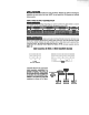
INVERTER OPERATION DIP SWITCH SETTINGS (SUIOKPM SHOWN) Using a small tool, set the four Inverter Operation DIP Switches (located on the rear panel of your UPS, see pg. 4-5 for location) to match your input voltage, input frequency a n d desired operational mode. InDut Voltage Selection (D~P switch& # 1 ~r #2) (Input Voltage Select Terminal Block) These DIP switches and the Input Terminal Select Block must BOTH be set to match your input voltage. Your UPS WILL NOT CONVERT the voltage.
UPS LOCATION Move your UPS over short distances using its wheels. Stabilize the UPS by releasing the stabilizers on each side of the unit. NOTE: Do not stack the UPS Systems or external battery packs.
EXTERNAL BATTERY PACK CONNECTION (SUGK: Optional; SU1OK: Required) Since SUGK models contain internal batteries, connecting external battery packs (to extend runtime) is optional. SUlOKPM models, however. do not have internal batteries and require an external battery pack connection to a SUlOKBP or a SUBP.
BA77ERY CONDITION VERIFICATION When the UPS is operating from battery power, the alarm and LCD Display will both alert you to the UPS battery's charge condition. Batterv Charge Condition FULL Alarm Short Beep (every 2 seconds) LOW Short Beep (every 1/2 second) UNDER Continuous Beep E D Dis~lav ON BAlTERY BA'IT = XXV W o BA'ITERY LOW B A T = XXV W o BA'ITERY UNDER SHUT DOWN INITIAL BAVERY CHARGING (OPTIONAL) Your UPS System's battery is fully charged prior to shipping.
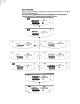
SELF-TESTING When you turn the UPS ON, it will perform a brief (about 25 second) self-test. See figure below for display sequence.' 'Note: ~ s t a r t i n g f i o mbattery, the BATIERY LED will be Ut and the I / P and BYPASS LED5 wlll MI. TheJInd LCD dlsplay In (he diagram below appears when the LlPS b operating normally under utfllty-supplledAC Input power. SELECT FREQ OUT .
LCD DISPLAY SELECT SWITCH Momentarily press the "SELECT" switch on the front panel to browse through different power readings on the LCD Display. The LCD Display will show which one of four operational modes your UPS is currently in: Normal, Economy, On-Battery, or Bypass. Also, a s you press the "SELECT"switch, the LCD Display will browse through load. input, bypass, output and battery conditions.
BATERY CHARGE WARNlNGS Since your UPS can provide battery backup only for a s long a s the batteries remain charged, these warnings should be acted on immediately. Battery Charge Warning LCD Display Message Battery charge nearly depleted BATTERYLOW AC/DC charger not operating CHARGERFAILURE! OPERATION UNDER SHUTDOWN Your UPS will shut down and the LCD will display a message if it detects one of the following conditions.
RS-232 INTERFACE This female DB9 port connects your UPS via an RS-232 cable to a workstation or server equipped with Tripp Lite software. The port uses RS-232 communications to report UPS status and power conditions. Using this port, M p p Lite software can monitor and manage network power and automatically save open files and shut down equipment during a blackout.
DRY CONTACT INTERFACE: This female DB9 contact-closure port allows your UPS to send contact-closure signals to indicate that it is on battery back-up mode and if its batteries are running low. The port can also receive a remote shutdown signal. Pin assipnment; - lmin.U.3mA LOW BATTERY I b NC If I COY I C REMOTE SHUTDOWN SIGNAL FROM EXTERNAL 1 I SIGNALFROM COMPUTER .
Service Your Smartonline UPS is covered by the 2-year limited warranty period described below. A variety of service contracts is also available from Tripp Lite. including startup service contracts and 3- to 5-year SafeSure on-site service contracts. For more information, call Tripp Lite Customer Service at (773)869-1233.
ACINPUT SURGE - PROTECTOR *' * INPUT FILTER ,A C T 0 DC CONVERTER - DCTOAC INVERTER I I dLs dLt 120 VAC INPUT STATIC BYPASS SW~CH - OUTPUT FILTER - MANUAL BYPASS SWITCH OUTPUT - lSoLATIoN - XFM I - STANDARD BAllERIES: 240 VDC SUBP EXTERNAL BATTERY CABINET(S): 240 M C - - CHARGER POWER SUPPLY CPU CONTROLLER -LEDS L C -TO D RS-232 As400 DRY CONTACT ACCESSORY SLOT REP0 BREAKER
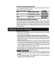
(Notc:Excludingisolation transformer) Model && SU6K SUlOK Inputvoltage Input Frequency 156V-280VSlngle Phase 50/60 Hz t 3 Hz (selectable, pg. 7) 32A <150A ~0.99 >87Oh 40A 156V-280VSinglePhase 50/60 Hz 2 3 Hz (selectable. pg. 7) 50A <200A >0.99 >88% 63A 6000 4200 Slnewave Sinewave 120/208/240V 50/60 Hz (20.2 HZ on battery) k3Oh 10000 7000 Slnewave Slnewave 120/208/240V 50/60 Hz (20.2 Hz on battery) 23Oh ~ 3 % <6% 102% (continuous) 102%-125Oh (1 min.) 125%-150°h (30 sec.) > 150% (2 sec.