e nc Y ha ct NT IONr a c rodu y A R AT fo e p ant AR STRoday p Lit warr W I t rip m/ G ne T o RE nli EE .c o R lite er F p st in a .trip i g Re to w ww w Installation Manual Self-Contained Air Conditioning Unit Models: SRCOOL33K, SRXCOOL33K Table of Contents 1. Important Safety Instructions 2 7. Electrical Connections 5 2. Preparing the Installation Site 2 8. Network Card Connections 7 3. Positioning the Unit 2 9. Additional Contact Connections 8 4. Leveling the Unit 2 5.
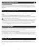
1. Important Safety Instructions SAVE THESE INSTRUCTIONS This manual contains instructions and warnings that must be followed during the installation of the products described in this manual. Read ALL instructions before attempting to install these products. Failure to comply may invalidate the warranty and cause serious property damage and/or personal injury. Also see the safety instructions contained in the SRCOOL33K/SRXCOOL33K Unpacking Instructions and Owner’s Manual. 2.
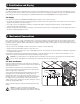
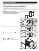
5. Stabilization and Baying 5.1 Stabilization For additional stability, the two shipping brackets and their associated hardware may be used to secure the unit to mounting points on the floor. Using a 13 mm open-end wrench, connect the brackets to the outer or inner bracket mounting points of the unit. Attach the brackets to mounting points on the floor using Tripp Lite’s SmartRack Bolt-Down Kit (model SRBOLTDOWN) or user-supplied hardware. 5.
6. Mechanical Connections 6.2 Ducting to Outside Environment If required, the SRCOOL33K/SRXCOOL33K can be ducted to the outside environment. Additional hardware for this application must be user supplied; it is not included with the unit. The following requirements apply: • Additional 250 mm (10-in.
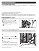
7. Electrical Connections The SRCOOL33K is a corded device that comes with an L6-30 cord assembly. This cord set can be removed for an optional hardwire installation. The SRXCOOL33K has connections for hardwire service or a user supplied input cord assembly. 7.1 Swapping Input Power Cord Connection (SRCOOL33K only) The SRCOOL33K is furnished with two points of possible mains power input, one at the top of the unit and one at the bottom.
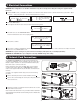
7. Electrical Connections 6 Insert cord assembly E and connect to the top terminal block F . G 7 Fasten screws G holding the assembly in place. E F 6-7 7 Reinstall the cover D from the top of the unit on the bottom in order to close access to the terminal block. D 7 8 Reinstall terminal block cover A . 9 Reinstall side panel. Aways connect plugs to a properly grounded, compatible outlet. Do not connect the plug to a power strip or surge suppressor. A 8 7.
. Electrical Connections WARNING! This configuration is for hardwire installations only/ Do not change this setting when using the supplied L6-30P input cord. From the HOME screen, scroll right to the SETUP screen and unlock the SETUP menus. To unlock SETUP press ENT > Open menus, Password > enter your password > SET. The default password is 000000.
9. Additional Contact Connections The SRCOOL33K/SRXCOOL33K includes an additional set of connectors A that allow you to connect to your facility’s Remote Emergency Power Off (EPO) circuit and provide additional leak detection, alarm and run contacts. Connecting the unit to the EPO circuit enables remote emergency shutdown of the unit. Connect EPO input to a user-supplied remote switch, following the circuit diagram below. This contact is normally open.
Manual de Instalación Unidad Autónoma de Aire Acondicionado Modelos: SRCOOL33K, SRXCOOL33K Índice 1. Instrucciones de Seguridad Importantes 2. Preparación del Sitio de Instalación 10 3. Posicionado de la Unidad 10 4. Nivelado de la Unidad 10 5. Estabilización y Alineado 11 6. Conexiones Mecánicas 11 10 7. Conexiones Eléctricas 13 8. Conexiones de la Tarjeta de Red 15 9. Conexiones de Contactos Adicionales 20 English 1 Francais 17 Русский 25 MÁS DE 1111 W.
1. Instrucciones de Seguridad Importantes GUARDE ESTAS INSTRUCCIONES Este Manual contiene instrucciones y advertencias que deben observarse durante la instalación de los productos descritos en este manual. Lea TODAS las instrucciones antes de intentar instalar estos productos. El no hacerlo puede invalidar la garantía y causar serios daños a la propiedad y/o lesiones personales.
5. Estabilización y Alineado 5.1 Estabilización Para una estabilidad adicional pueden usarse las dos ménsulas de embarque y sus accesorios asociados para asegurar la unidad a puntos de instalación en el piso. Usando una llave de tuercas de 13 mm, conecte los soportes a los puntos de instalación externos o internos de la unidad. Fije los soportes a puntos de instalación seguros del piso con herramientas suministradas por el usuario o con el kit de pernos para SmartRack de Tripp Lite (modelo SRBOLTDOWN). 5.
6. Conexiones Mecánicas 6.2 Conductos al Ambiente Exterior Si se requiere, el SRCOOL33K/SRXCOOL33K puede conectarse al ambiente exterior. Los accesorios adicionales para esta aplicación deben ser suministrados por el usuario; no están incluidos con la unidad. La siguiente lista es aplicable: • Pueden necesitarse tubos adicionales de 250 mm (10 pulg.
7. Conexiones Eléctricas El SRCOOL33K es un dispositivo cableado que viene con un cable L6-30 instalado. Este cable puede removerse para una instalación opcional con cableado permanente. El SRXCOOL33K tiene conexiones para cableado permanente o un cable de alimentación proporcionado por el usuario. 7.1 Conexión intercambiable de cable de alimentación (SRCOOL33K solamente) El SRCOOL33K está equipado con dos puntos de posibles alimentaciones, uno en la parte superior de la unidad y otro en la parte inferior.
7. Conexiones Eléctricas 6 Inserte el ensamblaje del cable E y conecte al bloque superior de terminales F . G E F 6-7 7 Apriete los tornillos G que sujetan el ensamblaje en su sitio. 7 Reinstale la cubierta D de la parte superior de la unidad en la parte inferior a fin de cerrar el acceso al bloque de terminales. D 7 8 Reinstale la cubierta del bloque de terminales A . 9 Reinstale el panel lateral. Conecte siempre las clavijas a un tomacorrientes compatible, apropiadamente conectado a tierra.
7. Conexiones Eléctricas ¡ADVERTENCIA! Esta configuración es sólo para instalaciones eléctricas permanentes / No cambie esta configuración al usar el cable de alimentación 16_30 suministrado. 1 Desde la pantalla HOME, desplacese a la derecha hasta la pantalla SETUP y desbloquee los menús SETUP . Para desbloquear los menúes de SETUP, oprima ENT > Open Password > ingrese su contraseña > SET.
9. Conexiones de Contactos Adicionales El SRCOOL33K/SRXCOOL33K incluye un juego adicional de conectores A que le permiten conectar a su circuito de Apagado de Emergencia (EPO) remoto y proporcionan contactos adicionales para detección de fugas, alarma y funcionamiento. El conectar la unidad al circuito EPO permite el apagado de emergencia remoto de la unidad. Conecte la entrada del EPO a un interruptor remoto suministrado por el usuario, de acuerdo al siguiente diagrama de circuito.
Manuel d'installation Climatiseur de type armoire Modèles : SRCOOL33K, SRXCOOL33K Table des matières 1. Directives de sécurité importantes 18 7. Connexions électriques 21 2. Préparation du site de l'installation 18 8. Connexions de la carte réseau 23 3. Mise en place de l'unité 18 9. Connecteurs additionnels 24 4. Mise à l'horizontale de l'unité 18 5. Stabilisation et mise en place 19 6. Raccordements mécaniques 19 English 1 Español 9 Русский 25 1111 W.
Directives de sécurité importantes CONSERVEZ CES INSTRUCTIONS Le présent manuel contient des instructions et des avertissements qui doivent être suivis durant l’installation des produits décrits dans ce manuel. Lire TOUTES les instructions avant de tenter d’installer ces produits. Le non-respect de ces instructions peut annuler la garantie et causer des dommages graves à la propriété et/ou des blessures.
5. Stabilisation et mise en place 5.1 Stabilisation Pour une stabilité additionnelle, les deux supports d'expédition et la quincaillerie associée peuvent être utilisés pour sécuriser l'unité à des points d'ancrage au plancher. Au moyen d'une clé à fourche de 13 mm, fixez les supports aux points de montage des supports externes ou internes de l'unité.
6. Raccordements mécaniques 6.2 Conduits vers l'environnement extérieur Au besoin, le SRCOOL33K/SRXCOOL33K peut être équipé de conduits acheminés vers l'environnement extérieur. La quincaillerie additionnelle pour cette application devra être fournie par l'utilisateur, elle n'est pas incluse avec l'unité. Les exigences suivantes s'appliquent : • Des conduits de 250 mm (10 po) de diamètre peuvent être requis.
7. Connexions électriques Le SRCOOL33K est un dispositif avec fil qui est fourni avec un cordon amovible L6-30. Ce cordon amovible peut être enlevé pour une installation câblée facultative. Le SRXCOOL33K comporte des connexions pour le service câblé ou un ensemble de cordons d’entrée fourni par l’utilisateur. 7.
7. Connexions électriques 6 Insérez le cordon E et branchez-le au bornier supérieur F . G 7 Serrez les vis G retenant le cordon en place. E F 6-7 7 Réinstaller le couvercle D du haut de l'unité au bas de l'unité pour empêcher l'accès au bornier. D 7 8 Réinstallez le couvercle du bornier A . 9 Réinstallez le panneau latéral. Branchez toujours les fiches à des prises compatibles, adéquatement mises à la terre. Ne branchez jamais la fiche à une multiprise ou à un parasurtenseur. A 8 7.
7. Connexions électriques AVERTISSEMENT ! Cette configuration ne s'applique qu'aux installations à raccordement fixe. Ne changez pas ce réglage lorsque vous utilisez le cordon d'alimentation L6-30P fourni. les 1 À partir de l'écran HOME, défilez vers la droite à l'écran SETUP et déverrouillez les menus SETUP.
9. Connecteurs additionnels Le SRCOOL33K/SRXCOOL33K est équipé d'un groupe de connecteurs additionnels A qui vous permettent de vous brancher au circuit externe d'arrêt d'urgence (EPO) de vos installations; il offre aussi des contacts additionnels pour détecter les fuites, les alarmes et le fonctionnement. Le branchement de l'unité au circuit « EPO » permet sa commutation hors tension à distance en cas d'urgence.
Руководство по монтажу Автономный кондиционер Модели: SRCOOL33K, SRXCOOL33K Содержание 1. Важные указания по технике безопасности 26 7. Электрические соединения 29 2. Подготовка места монтажа 26 8. Разъемы для подключения сетевых карт 31 3. Расположение устройства 26 9. Дополнительные контактные разъемы 32 4. Выравнивание устройства 26 5. Фиксация и встраивание в секцию 27 6. Механические соединения 27 English 1 Español 9 Francais 17 1111 W.
1. Важные указания по технике безопасности СОХРАНИТЕ ДАННЫЕ УКАЗАНИЯ В настоящем руководстве содержатся указания и предупреждения, которые необходимо соблюдать в процессе установки описанных в нем изделий. Просьба ознакомиться со ВСЕМИ указаниями до начала установки данных изделий. Несоблюдение этих указаний и предупреждений может привести к аннулированию гарантии и причинить существенный материальный ущерб и/или вред здоровью людей. См.
5. Фиксация и встраивание в секцию 5.1 Фиксация В целях придания дополнительной устойчивости возможно использование двух транспортировочных кронштейнов с соответствующими крепежными элементами для крепления устройства к опорным точкам пола. С помощью простого гаечного ключа на 13 мм прикрепите кронштейны к внешним или внутренним опорным точкам устройства. Прикрепите кронштейны к опорным точкам пола с помощью комплекта для болтового крепления SmartRack марки Tripp Lite (мод.
6. Механические соединения 6.2 Отвод воздуха во внешнюю среду В случае необходимости устройство SRCOOL33K/SRXCOOL33K может быть соединено воздуховодами с внешней средой. В этом случае от пользователя могут потребоваться дополнительные крепежные элементы, не входящие в комплект поставки.
7. Электрические соединения Модель SRCOOL33K представляет собой кабельное устройство, комплектуемое шнуром с разъемом L6-30 в сборе. Этот шнур может быть отсоединен для опциональной установки жесткого кабельного подключения. Устройство мод. SRXCOOL33K оснащается разъемами для жесткого кабельного подключения или подключения через предоставляемый пользователем входной шнур с разъемом в сборе. 7.1 Изменение места подключения входного шнура питания (только для мод. SRCOOL33K) Устройство мод.
7. Электрические соединения 6 Вставьте шнур E и подсоедините его к верхней клеммной колодке F . G 7 Затяните винты, G фиксирующие шнур. E F 6-7 7 Переустановите крышку D с верхней части устройства вниз с целью закрытия доступа к клеммной колодке. D 7 8 Установите на место крышку клеммной колодки A . 9 Установите на место боковую панель. Обязательно включайте электрические вилки только в заземленные и подходящие для них розетки. Не включайте вилку в удлинитель или сетевой фильтр. A 8 7.
7. Электрические соединения ВНИМАНИЕ! Данная схема используется только для установок с жестким кабельным подключением / Не меняйте данную установку при использовании шнура электропитания L6-30P, поставляемого в комплекте. 1 Из экрана HOME прокрутите вправо до появления экрана SETUP и разблокируйте меню SETUP.
9. Дополнительные контактные разъемы В состав устройства SRCOOL33K/SRXCOOL33K входит дополнительный набор разъемов, A что позволяет производить подключение к установленной на вашем объекте системе дистанционного аварийного отключения (EPO), а также иметь контакты для подключения дополнительных устройств обнаружения утечек, сигнализации и выполнения команд. Подключение устройства к цепи EPO обеспечивает возможность его дистанционного аварийного отключения.