
Owner`s manual


6
5
4
LOAD L2
BANK 1
3
1211
10
B4
B3
9
87
LOAD L1
BANK 2
LOAD L3
BANK 1
LOAD L2
BANK 1
STATUS
LINK
RESET
ENVIROSENSE
CONFIG
2-2
2-3
2-4
B
2-5
A
A B
6
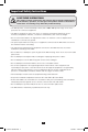
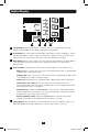
Installation
2-2
Connect the input plug to your facility’s
compatible AC power source.
2-3
Connect your equipment’s input plugs to
the appropriate outlets on the PDU. The
LED near each outlet illuminates when
the outlet is ready to distribute live
AC power.
Note: It is recommended that you do not
connect a live load to the PDU. If the load you
intend to connect has an ON/OFF switch, please
turn the switch to OFF prior to connection.
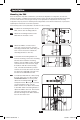
2-4
Optional Cord Retention Procedure
Option 1 (Select Models): Use
the bridge lances located near each
receptacle to retain power cords. Tie
each equipment power cord to a bridge
lance by looping the cord and securing
it with one of the included cable ties
A
.
Make sure each cord can be unplugged
from the PDU without removing the
cable tie.
Option 2: Use the included C14 and
C20 plastic sleeves to secure plugs to
receptacles. Attach the sleeve to the
plug, making sure that the pull tabs
B
remain outside the plug and that the t
is secure. To unplug equipment properly,
use the pull tabs to remove the plug
and sleeve from the receptacle.
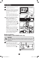
For Installation
Purposes Only
Hardwire Installations
(PDU3XVSRHWA & PDU3XVSRHWB models only)
2-5
These models do not come equipped
with an input cable. Conduit and
adapters are installed to the endplate
A
,
wires are channeled through the conduit
and adapters to the terminal block,
located behind the access plate
B
.
WARNING
Only qualied personnel should perform hardwire installations. Wire codes and
requirements differ from area to area. Be sure to conform to local electrical
requirements.
13-09-017-9332B8.indb 6 9/5/2013 4:26:49 PM