
Owner`s manual


CONFIG
A B
17
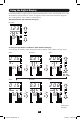
Features
SNMP Reset Button: Press the reset button for 3 seconds to reboot the
PDU’s network card. Rebooting the network card will not erase network
settings or interrupt AC power.
PS/2 Port: Use this port to connect a Tripp Lite ENVIROSENSE
environmental sensor to provide remote temperature/humidity monitoring
and a dry contact interface to control and monitor alarm, security and
telecom devices. Visit www.tripplite.com for ordering information. Note:
Do not connect a keyboard or mouse to this port.
Ground Screw: Use this to connect any equipment that requires a
chassis ground.
C20 Plug-lock Insert: (Optional) Use the included C20 inserts to secure
plugs to receptacles. Attach the insert to the plug making sure that the
pull tabs remain outside the plug and that the t is secure. To unplug
equipment properly, use the pull tabs to remove the plug and insert from
the receptacle.
RJ-45 Conguration Port: Use this port to provide a direct terminal
connection to a computer with a terminal emulation program. An RJ-45 to
DB9 cable (part number 73-1243) is included with the PDU. If you need
a replacement cable, visit www.tripplite.com for ordering information.
Note: Configuration options can found in the SNMPWEBCARD installation
guide on the included CD or at www.tripplite.com/manuals.
Ethernet Port: Use this RJ-45 jack to connect the PDU to the network
with a standard Ethernet patch cable. The Link LED
A
and Status LED
B
indicate several operating conditions, as shown in the table below. This
port is not compatible with PoE (Power Over Ethernet) applications.
Network Operating Conditions
A
Link LED Color
Off No Network Connection
Flashing Amber 100 Mbps Network Connection
Flashing Green 10 Mbps Network Connection
B
Status LED Color
Off Card Not Initialized
Steady or Flashing Green Card Initialized and Operational
Steady Amber Error - Card Not Initialized
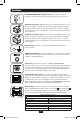
PDUMVROTATEBRKT Mounting Accessory: Use these V-shaped
brackets to mount the PDU with its outlets facing the rear of the rack.
C14 Plug-lock Insert: (Optional) Use the included C14 inserts to secure
plugs to receptacles. Attach the insert to the plug making sure that the
pull tabs remain outside the plug and that the t is secure. To unplug
equipment properly, use the pull tabs to remove the plug and insert from
the receptacle.
13-09-017-9332B8.indb 17 9/5/2013 4:26:59 PM