
User guide


SMART 216 / 232
5
6. The Smart 216 unit
Figure 1 illustrates the front panel of the Smart 216.
Figure 1 Smart 216 ports – side 1
6.1 LED and button table
LED Function
Power
Power Indicator
Link
Unit is connected to the network
Remote 1 and 2
Illuminates when the respective user connects to a server
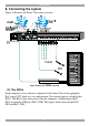
Figure 2 Smart 216 ports – side 2
6.2 Connector table
Connector Function
User 1 and User 2
KVM consoles
Connect 2 KVM consoles for two users to operate the Smart 216
RPS
Connect Minicom’s Serial Remote Power Switch
LAN
To configure and update the unit, connect to 10/100 Mbit
Ethernet.
Server ports
Connect to servers via ROCs
MINICOM
Power RemoteLink
SMART 216 A
21
Power
POWER
100-240 VAC 50/60 Hz
Server ports
I
0
1 2 3 4 5 6 7 8
Keyboard
Mouse
Monitor
USER 1
LAN (Ethernet)
port
LAN
RPS
Remote Power
Switch (RPS)
port
10 11 12 13 14 15 169
SERVER
Keyboard
Mouse
Monitor
USER 2