
Owner`s manual


7
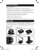
Remote Repeater Installation
7
Connect the external power supply to the repeater and plug it into a
Tripp Lite Surge Suppressor, PDU, or UPS. The Green Power LED and the
Green RJ45 LEDs illuminate to indicate the unit is receiving power.
Add up to 3 repeaters per channel, for a total of 4 displays (an active remote
receiver should be the last unit in a channel). To connect additional repeaters,
proceed to step 8. To finish your installation with a B140-1A0 or
B140-1A0-WP receiver, proceed to step 11.
8
Using Cat5e/6 cable, connect the RJ45 output port on the first repeater to
the RJ45 input port on a second repeater.
9
Connect a monitor to the DVI output port on the repeater using a Tripp Lite
P561-Series DVI-D Single-Link cable.
10
Connect the external power supply to the repeater and plug it into a
Tripp Lite Surge Suppressor, PDU, or UPS. The Green Power LED and the
Green RJ45 LEDs illuminate to indicate the unit is receiving power.
To add a third repeater, repeat steps 8 through 10. To finish your installation
with a B140-1A0 or B140-1A0-WP receiver, proceed to step 11.
11
Using Cat5e/6 cable, connect the RJ45 output port on the last repeater to
the RJ45 input port on a B140-1A0 or B140-1A0-WP receiver.
12
Connect a monitor to the DVI output port on the receiver using a
Tripp Lite P561-Series DVI-D Single-Link cable.
13
Connect the external power supply to the active receiver unit, and plug it
into a Tripp Lite Surge Suppressor, PDU, or UPS. When receiving power,
the Green RJ45 LED on the B140-1A0, and the Green Power LED on the
B140-1A0-WP, will illuminate.
Repeat steps 5 through 13 for each RJ45 output port on the B140-002-DD.
Note: See Note number 3 at the beginning of the Remote Repeater Installation section, and
reference the installation diagram to ensure the correct video signals are transmitted to the
monitors in your dual display installation.
13-01-085-933287_revA.indd 7 1/30/2013 3:44:20 PM