8150 CAMVIEW5 CCTV TESTER User Manual Thank you for purchasing the IP camera tester. Please read the manual before using the IP camera tester. Please first read the「Safety Information」carefully in the manual. The manual should be kept with unit in case reference is needed. Keep the S/N label for after-sale service within warranty period. Product without S/N label will be charged for repair service.
CCTV TESTER User Manual 1. Safety information .....................................................................................................1 2. IP Camera Tester Introduction ...................................................................................1 2.1 General ..............................................................................................................1 2.2 Packing list ........................................................................................................
CCTV TESTER User Manual 1. Safety information ◆ The tester is intended for use in compliance with the local rules for electrical testers. ◆ To prevent the functional failure, the product should not come in contact with water. ◆ The exposed part of the tester should not be exposed to any liquids. ◆ During transportation and use, avoid vibration of the tester. ◆Do not leave the tester unattended while charging.
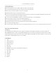
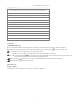
CCTV TESTER User Manual 2.3 Function interface 1 Menu key 2 Confirm key 3 Return: Return or cancel while setting parameters of the menu 4 4x zoom the image display 5 LED light The RS485 data transmission and received indicator lights red while the data is 6 being transmitted or received.
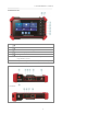
CCTV TESTER User Manual 8 Press more than 2 seconds to turn on or off, short press to turn on or off the menu display 9 Micro SD card removeable, supports up to 32G 10 DC12V 3A power output, temporarily supply power to the camera 11 PoE power supply output/LAN test interface 12 HDMI output 13 Video image /AHD/TVI/CVI signal input(BNC interface) 14 LED lamp 15 DC 12V 1A charging interface 16 RS485 Interface: RS485communication for PTZ control 17 Audio input 18 UTP cable port: UTP cable
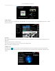
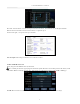
CCTV TESTER User Manual 4.2 IPC Test pro Camera test often needs to open multiple apps, "IPC TEST PRO" app, using new technology and combing multiple functions into one APP, can increase efficiency. Application: Support multi-segment IP address scan, can visually display camera brand, click IP address to display the image. Can supply the power to PoE camera. Real-time display network port connection status. Use one key to connect camera test tool, browser can login and configure camera.
CCTV TESTER User Manual Local IP: Tester’s IP address, Tester can auto-modify the tester’s IP to the same network segment with the scanned camera's IP. Discovery IP: Connected tester equipment’s IP address. If the camera is connected to the tester directly, the tester will display the camera’s IP address, if the tester connects to Local Area Network, it displays the current IP address. Start: PING function, click "Start", can PING camera’s IP. ONVIF: Rapid ONVIF Quick link.
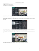
CCTV TESTER User Manual Confirm: Save the modified parameters. Click “MENU” icon to open camera setting. While in the “Live video” menu, click “Video Menu” at the top right of the image to access the following tools: Snapshot, Record, Photo, Playback, Lens simulation, PTZ and Settings. Network setting: Click “Network Set” to change the IP address. Some cameras cannot support change IP address, so there is no change after saving.
CCTV TESTER User Manual After selecting a channel, you can edit the channel name, modify the display position, and switch the font size. Select “Content location Default location”. Select “Customize” to arbitrarily adjust the channel name and display location. Click “OK” to save the modification. Press return key or click any area on the screen to return to the previous interface. Video files can play in the Video player on the main menu.
CCTV TESTER User Manual Doc: Click "Create document”, to create a test report document for the camera, . Click “Preview” to view the report document Enter the camera test information, click "Create Document" to complete the report. Click doc menu again, you can preview the report document. Icons description: The description of function icons on the bottom toolbar. 4.5 Non-OnVIF IP camera test Display image from the 4K H.265 camera by mainstream.
CCTV TESTER User Manual IP camera type: Click on the IP Camera type to select the manufacturer and model number of the connected IP camera. Manual: Click IP camera type, list Honeywell, Kodak, Tiandy, Aipu-waton, ACTi, WoshiDA IP camera etc. If the brand has official original protocols, pls select camera type, input IP camera address, username and password, click “official” to enter the camera image display interface.
CCTV TESTER User Manual 5.3 CVI camera test When HD CVI signal input, the tester will display the image resolution at the top of the screen. Double tap on the screen to display the image in full screen. The tester supports resolution up to 3840 x 2160P 12.5/15 FPS. (1)PTZ control 1.1 Coaxial PTZ control Click the icon “PTZ” on the right toolbar to do the corresponding setting. “Port”: select coaxial control Enter PTZ address to perform parameters setting.
CCTV TESTER User Manual (2)Coaxial camera menu setting Input calling dome camera menu address code, you can press the key “Enter” or click the icon to call the dome camera menu. set the parameters by 5.4 TVI camera test When using an HD TVI signal input, the tester will display the image resolution at the top of the screen. Double tap on the screen to display the image in full screen. The tester supports resolution up to 3840 x 2160P 12.5/15 FPS.
CCTV TESTER User Manual Input calling dome camera menu address code, after finishing the parameter settings, you can press the key “Enter” or click the icon call the dome camera menu. 5.5 AHD camera test When using an AHD signal input, the tester will display the image resolution at the top of the screen. Double tap on the screen to display the image in full screen. The tester supports resolution up to 3840 x 2160P 15 FPS.
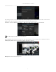
CCTV TESTER User Manual 6.1 Network tool (1) IP address scan Connect the cable to the LAN port, click icon to enter, set your IP address search range by changing the Start and End IP addresses. Click the “Start” button to scan the IP address range. You can also input an IP address in the Port Number Scan to scan for open ports. (2) PING Test Application: PING testing is the most conventional network debugging tool. It is used for testing if the connected.
CCTV TESTER User Manual (6) Trace route It is used to determine the path of the IP packet access target. Note: Trace route testing results only for reference, for accurate test route tracking, use a professional Ethernet tester. (7) Link monitor This app is used to see if an IP address is occupied by other network devices. This will avoid new address conflicts. 6.2 RJ45 cable TDR test Connect cable to tester’s LAN port, click icon “ ” to enter app. Single test: Test cable status, length and attenuation.
CCTV TESTER User Manual Test LAN cable or telephone cable. Connect LAN cable or telephone cable with the CCTV tester and cable tester. And then the connecting status, cable type and the sequence of wires as well as the serial number of the cable tester kit will be displayed. The number of the cable tester is 255.
CCTV TESTER User Manual 1. Do not input power into the “DC12/3A OUTPUT” port. 2. Do not output the DC12V/3A power into the DC12V/IN port of the IP camera tester. 3. The IPC tester power output is close to 3A, if the IP camera’s power is over 3A, the tester will auto enter protection mode. Disconnect all tester connections and then connect the tester with the power adaptor to continue. 4. Before turning on the PoE power output, make sure the IP camera supports PoE power.
CCTV TESTER User Manual You can choose internal or external SD card. For other operation details, refer to FTP settings. 6.7 System Setting Language: Select your desired language: English, Chinese, Korean, Russian, Italian, Polish, Spanish, French or Japanese. Typewriting: You can select typewriting or install other typewriting: Date/Time: Set the Date/time of the IP tester. IP setting: Manually set the IP address, Subnet Mask, Default Gateway and DNS address or select “Dynamic allocation” to use DHCP.
CCTV TESTER User Manual Brightness: Set the desired brightness of the IP tester and adjust the sleep time settings. Volume: Set volume level SD Card: Displays SD Card Capacity. You can also format the SD card or unmount it before removing it. FTP server: Once the IP tester connects to a network, a computer can be used to read the SD card files via FTP. Start the FTP server and then input the tester’s FTP address in the PC’s address bar.
CCTV TESTER User Manual 6.8 HDMI out The built in HDMI output port can output live video from an analog or IP camera, recorded files, media files and images to HDTV monitors. Connect an HDMI cable from the IP tester to an HDTV monitor at any time. It supports up to 3840x2160P 30FPS resolution. 7. Specifications 7.1 General Specifications Model Display Network port WIFI 8150 Camview5 Security Camera Tester New 5.
CCTV TESTER User Manual 2048x1536p 18/25/30fps, 1920x1080p 25/30fps, 1280x720p 25/30/50/60fps, UTC control and call OSD men 1 channel AHD input(BNC interface), resolution support 8MP AHD camera test, AHD video signal test 3840 x 2160P 15 FPS, 2592x1944p12.
CCTV TESTER User Manual Working Temperature Working Humidity Dimension/Weight -10℃---+50℃ 30%-90% 183mm x 110mm x 36.5mm /0.
User Manual SBR2M Security Camera Tester Borescope 2M (6.
Introduction Congratulations on your purchase of the Triplett SBR2M Security Camera Tester Borescope. This borescope paired with any security camera tester adds a borescope function to your security camera tester. Features • • • • • • • Waterproof (IP67) 8mm camera (Lens only) 2m cable (6.
Operation 1. 2. 3. 4. 5. Locate the gender changing cables (for BNC and Power) supplied with your security camera accessory kit. Install onto the SBR2M. Connect to BNC Video IN and 12/1,2 or 3A Power output on the security camera tester. Click on Auto HD and the video will be displayed. Follow instruction for taking images and video as you would on your model camera tester.
Specifications SBR2M Camera 8mm Field of View 60° Depth of View 1.2 to 4" (3 to 10cm) Cable Length 2m (6.5ft) Resolution 640 x 480 Illumination 6 adjustable LEDs Still Image Capture dependent on camera tester Video Recording dependent on camera tester Power Interface Dimensions Weight 12V 1/2/3A (provided by camera tester) BNC Camera & Cable: 6.5ft x 0.3” (2m x 8mm) LED Thumbwheel: 2x0.5x0.25" (51x13x6.4mm) 5.