
User's Manual


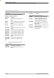


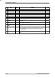
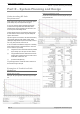
Table Of Contents
- Part A – Preface
- Warranty
- Important Notice
- FCC Compliance Notices
- Australian Compliance Notices
- Other Related Documentation and Products
- Revision History
- Part B – O Series Overview
- Definition of O Series Data Radio
- O Series Product Range
- O Series – Features and Benefits
- Standard Accessories
- Part C – Applications
- Application Detail
- Part D – Module Pinouts
- Part E – System Planning and Design
- Understanding RF Path Requirements
- Examples of Predictive Path Modelling
- Selecting Antennas
- Power Supply and Environmental Considerations
- Part F – Mounting and LED Indicators
- Mounting
- Antenna Port Cabling
- Product Labelling
- LED Indicators
- Part G – Specifications
- Appendix – FCC Approved Antennas

Page 8 © Copyright 2007 Trio DataCom Pty. Ltd.
O Series Data Radio – User Manual
Pin Name
In/Out
Comment Level
1 PORT2-TxD I Input for transmit for Port 2 [Port A on K-Series] 3.3V TTL
2 PORT2-RxD O Output for received data for Port 2 [Port A on K-Series] 3.3V TTL
3 PORT2-CTS O Flow control of TxD for Port 2 [Port A on K-Series] 3.3V TTL
4 PORT2-RTS I Flow control of TxD for Port 2 [Port A on K-Series] 3.3V TTL
5 PORT2-DTR I Flow control of RxD for Port 2 [Port A on K-Series] 3.3V TTL
6 VCC I 3.3V Supply Input 100mA +/-5%
7 SysSerIn I Diagnostics/FDL input data or Testmode command 3.3V TTL
8 SysSerOut O Diagnostics/FDL output or Testmode command 3.3V TTL
9 PORT2-DCD O Flow control of RxD for Port A 3.3V TTL
10 PAVCC I PA Supply Input (3.3V – 5V) 700mA @ 5V +/-5%
11 GND N/A
12 PAVCC I PA Supply Input (3.3V – 5V) 700mA @ 5V +/-5%
13 Analogue RSSI O Synthesised average of RSSI (20dB/V absolute reference TBD)
[can also be used as a general purpose analogue output]
0-2.5v
14 GND N/A
15 Tx_LED O Tx activity (Active Low) 3.3V TTL
16 Analogue Input I General purpose analogue input. 66k input resistance. 0-6v
17 Sync_LED O Masters: 100ms pulse when user data received (Active Low)
Remotes/Bridges: pulsed every 1500ms for 100ms when master acquired,
additional 100ms pulse when user data received (Active Low)
3.3V TTL
18 TxD_PORT1_LED O Pulsed for 100ms for any TxD activity for Port 1 [Port B on K-Series] (Active
Low)
3.3V TTL
19 RxD_PORT1_LED O Pulsed for 100ms for any RxD activity for Port 1 [Port B on K-Series] (Active
Low)
3.3V TTL
20 TxD_PORT2_LED O Pulsed for 100ms for any TxD activity for Port 2 [Port A on K-Series] (Active
Low)
3.3V TTL
21 RxD_PORT2_LED O Pulsed for 100ms for any RxD activity Port 2 [Port A on K-Series] (Active
Low)
3.3V TTL
22 Pwr_LED O DC power OK (Active Low) 3.3V TTL
23 nFACT/TEST-
MODE
I Reset factory defaults (Active Low on power-up) or
Test Mode (Active High on power-up) or
Neither (tri-state)
If this pin is pulled high once the unit is in a fatal error state the fatall error
condition will be indicated on the LED status lines.
3.3V TTL
24 PTT I Keys the radio at maximum TX/RX duty cycle using the current programmed
channel selection and output power (Active Low).
Note that while a radio is in this mode no data can be passed, the RSSI
indication on other units will not respond to the radio being PTT keyed and it
may block other systems.
3.3V TTL
25 TxInhibit I Tx inhibit for hot standby operation (Active High) 3.3V TTL
26 nSHUTDOWN_IN I Power down entire module (Active Low) 3.3V TTL
27 TxSync Input I Tx Sync input 3.3V TTL
Part D – Module Pinouts