
User's Manual
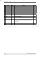
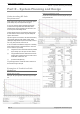


Table Of Contents
- Part A – Preface
- Warranty
- Important Notice
- FCC Compliance Notices
- Australian Compliance Notices
- Other Related Documentation and Products
- Revision History
- Part B – O Series Overview
- Definition of O Series Data Radio
- O Series Product Range
- O Series – Features and Benefits
- Standard Accessories
- Part C – Applications
- Application Detail
- Part D – Module Pinouts
- Part E – System Planning and Design
- Understanding RF Path Requirements
- Examples of Predictive Path Modelling
- Selecting Antennas
- Power Supply and Environmental Considerations
- Part F – Mounting and LED Indicators
- Mounting
- Antenna Port Cabling
- Product Labelling
- LED Indicators
- Part G – Specifications
- Appendix – FCC Approved Antennas

Page 15 © Copyright 2007 Trio DataCom Pty. Ltd.
O Series Data Radio – User Manual
Part E – Getting Started- O Series
LED Indicators
Indicators Legend
Power LED Tx Power (Red) / DC Power (Green)
Sync/NoRx LED Masters:
100ms pulse when user data received (Green)
Remotes/Bridges:
Pulsed every 1500ms for 100ms when master acquired, additional 100ms
pulse when user data received (Green)
Pulsed every 1500ms for 100ms when master not acquired (Red)
Port A Activity Pulsed for 100ms for any TxD activity on Port A TXD (Red)
Pulsed for 100ms for any RxD activity on Port A RXD (Green)
Port B Activity Pulsed for 100ms for any TxD activity on Port BA TXD (Red)
Pulsed for 100ms for any RxD activity on Port B RXD (Green)