User’s Guide TS 700-SS Digital Indicator Series 3 Version 3.0 11/15/10 Triner Scale & Mfg. Co.
!!!! CALIBRATION WARNING !!!! Calibration AND Inspection of calibration properties is prohibited unless done so by a qualified scale technician. WARNING The indicator is the static and sensitive equipment, cut off the power during electrical connections, internal components touched by hand is prohibited, and please take the measure of anti-static. © 2010 Triner Scale. All rights reserved.
Table of Contents Specifications __________________________________ 2 Load Cell Connections ___________________________ 3 Serial Port Connections __________________________ 4 Operation ______________________________________ 5 Parameters and Settings _________________________ 7 Data Output Formats ___________________________ 15 Error Codes ___________________________________ 19 Factory Default Settings _________________________ 20 1
Specifications Technical parameters Accuracy class 6000 e Resolution Display: 30, 000 Zero stability error TK0 < 0.1µV//K Span stability error TKspn < ± 6 ppm//K Sensitivity (internal) 0.
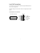
Load Cell Connections The indicator can connect with a maximum of eight of 350Ω load cells, 4 wire or 6 wire configurations. Excitation voltage for the load cell is 5VDC, the largest output current 120mA.
Serial Port Connection RS232 Terminal on Circuit Board DB9 2 3 5 Definition TXD RXD GND Function Sending data Receiving data Ground interface Note: if RS485, The connection pin is 2 and 5 pin.
Operation Keys and Their Functions KEY On/Off Hold Total OPERATION / FUNCTION Press and hold for 2+ seconds to operate. To Hold Weight on Scale - With weight on scale, press key to hold weight. To Hold Peak Weight of Multiple Weighings - Without weight on scale, press key to put indicator in peak hold mode. To Remove Hold Function - Press key again to return to normal operation. - With weight on scale, press key to place weight and count in memory.
item on scale, press Total to add weight to total weight and total count. kg/lb Gross Tare Zero Print - To view totals, press Total and Print key at the same time. The total weight will flash continuously. - To go out of view totals mode, press and hold the Total key. “Clr n” will display. - If you wish to continue adding to the totals, press the Print to accept the “Clear-No” prompt. Continue weighing and adding items as required.
Parameters and Settings CAUTION: Use care when accessing and adjusting your indicator’s parameters. Several parameters can be accessed that, if altered, will change your indicator’s operations. To access and adjust the TS-700 SS parameters: Press the PRINT and HOLD keys. “C” will display. Release the keys. “C08” will display, with the 8 flashing. The digit flashing is the active digit, and can be adjusted up or down by using the ZERO/UP ARROW or TARE/DOWN ARROW key.
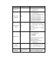
Function Setting Parameter C08 Warning tone Automatic power off C09 Power saving setting C10 Parameters Settings Options: 0 = no warning tone 1 = warning tone on Options: 0 = no auto power off 10 = power off automatically if no change within 10 minutes. 30 = power off automatically if no change within 30 minutes. 60 = power off automatically if no change within 60 minutes. Options: 0 = close power saving setting 3 = close display if no change within 3min. 5 = close display if no change within 5 min.
Inner Code display Date and time Communication setting C14 Lower limit alarm value C15 Enter C15 to check the inner code. C16 Date C17 Time C18 Serial interface data output method C19 Baud rate Zero range CAUTION; C20 Manually zero range Changing these parameters will effect the indicator’s performance. C21 Initial zero range 9 Enter C16, set the date, from left to right: year/month/day Enter C17, set the time from left to right: hour/min./sec.
C22 Automatically zero tracking range Zero tracking CAUTION; Changing these parameters will effect the indicator’s performance. C23 Automatically zero tracking time Overload range Negative display C24 CAUTION; Changing these parameters will effect the indicator’s performance. C25 1 = ±1% max capacity 2 = ±1% max capacity 5 = ±1% max capacity 10 = ±1% max capacity 20 = ±1% max capacity Options: 0 = disable zero tracking 0.5 = ±0.5d 1.0 = ±1.0d 2.0 = ±2.0d 3.0 = ±3.0d 4.0 = ±4.0d 5.0 = ±5.0d Note: 1.
Standstill time CAUTION; Changing these parameters will effect the indicator’s performance. Digital filter C26 Standstill time Options: 0 = quick 1 = medium 2 = slow Options: 1 = 1d 2 = 2d 5 = 5d 10 = 0d (d = division) C27 Standstill range CAUTION; C28 To compensate for unstable loads on the weighing platform (for example, animal weighing). CAUTION; C29 Noise filter Changing these parameters will effect the indicator’s performance.
Relay setting output Mutli communication add. Wireless communication C34 Communication add. C33 = 0 close relay output C33 = 1 Open relay output function 1 C3 = 2 Open relay output function2 C33 = 3 Preserved menu C34 = 0~99 Add. Code (RESERVED) C35 C35 = 0~99 signal (RESERVED) Gravity calibration location of C36 Gravity destination of Version No. Preserved menu C33 Relay output C36 = 9.7000~9.9999 CAUTION; Changing these parameters will effect the indicator’s performance. C37 C37 = 9.
Data Output Formats Remote Display Format Output continuous format S S S S T W W W X A B C 1 X X 2 X X X X X 3 X X X X X 4 C R 5 C K S 6 State A Bits0,1,2 0 1 2 1 0 0 XXXXXX0 0 1 0 XXXXXXX 1 1 0 XXXXX.X 0 0 1 XXXX.XX 0 1 XXX.XXX 1 Decimal point position Bits3,4 Division 0 1 X1 1 0 X2 State B BitsS function Bits0 gross=0, net=1 Bits1 Symbol: positive =0,negative =1 Bits2 Overload(or under zero)=1 Bits3 dynamic=1 Bits4 unit:lb=0, kg=1 B
Bit2 Bit1 Bit0 unit 0 0 0 Kg or lb 0 0 1 g 0 1 0 t Bit 3 printing=1 Extend Bit 4 display=1 Bit 5 Constant 1 Bit 6 Constant 0 PC Computer Continuous Sending Format , , S1 S2 CR S3 Data LF S4 S1: weight status, ST= standstill, US= not standstill, OL= overload S2: weight mode, GS=gross mode, NT=net mode S3: weight of positive and negative, “+” or ” –“ S4: “kg” or “lb” Data: weight value, including decimal point CR: carriage return LF: line feed Serial Interface Re
R command receive data format 5.4 Print format ID.NO. 004 (Serial No.) Date: XX.XX. XX (yy.mm.dd) Time: XX.XX.XX (hh.mm.ss) GROSS 8.88kg (gross weight) TARE 2.88kg (tare) NET 6.00kg (net weight) 5.
Error Codes ERROR UUUUUU nnnnnnn REASON 1. Overload 2. wrong connection with load cell 3. load cell has quality problem. SOLUTION 1. reduce the weight 2. check load cell connection 3. inspection load cell. Check the input and output 1. calibration is no good 2. wrong connection 3. load cell has quality problem 1. check scale is resisted or not, foot is kept level or not. 2. check load cell connection. 3. checking load cell : check input and output resistance to judge it is good or not.
Factory Default Settings Parameter instruction Default C01 Calibration 1 C02 Decimal digits 0 C03 Resolution 1 C04 Max.
C21 Initial zero 10 C22 Zero tracking range C23 Zero tracking time 1 C24 C25 C26 C27 C28 C29 C30 C31 C32 C33 C34 Overload range Negative range Standstill time Standstill range Dynamic filter Noisy filter Print format Analog signal options 4~20mA testing Relay output setting Muti PC communication add. 9 10 1 2 0 2 0 1 4 1 0 C35 C36 C37 C38 C39 Wireless communication channel 6 9.7936 9.7936 0.5 Calibration location gravity Destination gravity Version No.