MP-20 Thermal Printer Setup & Operation Manual Revision 1.3 July 17, 2003 2002-2003 Transcell Technology, Inc. Contents subject to change without notice. Transcell Technology, Inc. 975 Deerfield Parkway Buffalo Grove, IL 60089 Tel (847) 419-9180 Fax (847) 419-1515 E-mail: transcell@transcell.net Web: www.transcell.
IMPORTANT SAFETY INSTRUCTIONS * Read all of these instructions and save them for later reference. * Follow all warnings and instructions marked on the product. * Unplug this product from the wall outlet before cleaning. Do not use liquid or aerosol cleaners. Use a damp cloth for cleaning. * Do not use this product near water. * Do not place this product on an unstable cart, stand of table. The product may fall, causing serious damage to the product.
1. INTRODUCTION The MP-20 is a thermal printer suitable for use with various data communication devices. This product is extremely compact and features extensive functions suited for a wide range of applications. Please read this manual thoroughly to understand the printer before use. 1.1 Features 1. Compact desktop thermal printer 2. Light weight 3. High speed printing 4. Low power consumption 1.2 Accessories The following attachments are included in this set aside from the printer itself. Please confirm.
2. TYPE CLASSIFICATIONS 2.1 Type The product is categorized according to the naming plan indicated below. MP-20 Model Name Number of columns (default font) 20 : 20 columns/384 dots per line 2.2 AC adapter Please use the exclusive adapter indicated below. 250115288 (AC 100-240V) 2.3 Specifications Printing method Printing width Number of dots/line Dots density Printing speed Feeding speed Standard paper roll size (W x L) Interface Power Current consumption Weight Dimension (W x D x H) Operation temp.
3. EXTERNAL APPEARANCE AND PART DESCRIPTIONS 3.1 External Appearance 6 2 3 5 1 4 7 3.2 Part Descriptions 1. DC Power Jack: Insert one end of the enclosed AC adapter here. 5. Interface Connector: Printer is connected to various hosts via cables. Please ensure that both the printer and the host are turned off before connecting. 2. Power/Status Lamp: Lit when power is turned ON and goes out when turned OFF. Also used to indicate system status. See Section 3.3. 6.
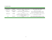
3.2 System Status Lamp Condition System Status Description Action Steady Green READY Send command or data to printer Flashing Green Steady Red PROCESSING CMDERR System ready to accept any command and data input System is processing a command(s) Command format error, or command/data buffer overflow Flashing Red SYSERR Amber PENDING Wait for process to finish Clear error state by pressing CLR key, and then resend all commands after the one that caused the error System error.
4. OPERATION 4.1 Connection of the AC Adapter (1) Connect interface cable between the printer and data communication device using supplied cable. (2) Plug the AC adapter into the DC power jack on the printer. (3) Plug of the AC adapter into a power outlet supplying the designated voltage. (Use of exclusive AC adapter is recommended. Output is DC 9V, 2.8A. Avoid using power sources not conforming to this specification.) The Power/Status Lamp should be green. 4.
4.4 General Notices (1) Never operate your printer without first loading thermal paper. Any printing without paper or with non-thermal paper may cause damage to printer head. (2) Be careful not to drop any foreign matter, such as paper clips, pins, etc. into your printer. These can cause mechanical and/or electrical problems. (3) Use your printer on a flat, stable desk. (4) Do NOT use an organic solvent (thinner, benzene or the like) to clean the surface of the case.
5. SERIAL INTERFACE 5.1 Specifications 1) Synchronization: Asynchronous 2) Baud rate: Fixed at 9,600 Baud / sec 3) Word configuration: Start bits: 1 Data bits: 8 (no parity) Stop bit: 1 4) Signal polarity RS-232C * Mark = Logic “1” (-3 to –12V) * Space = Logic “0” (+3 to +12V) 5) Handshaking control: None 5.2 Connector Pin Assignment 1 2 3 PIN No. PIN NAME FUNCTION 1 2 3 TXD RXD GND Transmitted data Received data Signal ground Note: 1. Signals for RS-232C are based on EIA RS-232C level.
6. Interface for MP-20 Mini Printer 6.1 Working Modes Name Character Mode (default): Description Prints one line of characters whenever a “carriage return” is received from serial port. Barcode Mode: Prints one line of barcodes whenever “carriage return” is received from serial port. Command-Line Mode: Accepts predefined command lines from serial port. Test Page Mode: Operates a batch of pre-input command lines to print a featured label.
6.3 Fonts Used (See Appendix A for sample print outs) Version 1.08 and higher: ARIAL Narrow 14 ARIAL 14 Bold ARIAL Narrow 20 ARIAL 20 Bold COURIER 20 Bold CHIBLACK 24 LUCIDA 16 Bold 1 2 3 4 5 6 7 Version 1.
6.4 Mode-Setting Commands (in effect for all modes): [ESC]@[ESC] Clear command error (function same as CLR key). [ESC]S[ESC] Get system status (return status from serial port). [ESC]M[ESC]mode Mode switching. [ESC]F[ESC]lines Feed lines (in dots). [ESC]P[ESC] Process from pending state. [ESC]H[ESC]headernumber Print header.2 Modes: 1 Character mode 2 Command Line mode 3 Barcode mode 4 Test Page mode 5 Configuration mode2 * When input an empty line (only [LF], or [CR][LF]), process [ESC]F[ESC]16.
6.5.
7. CHARACTER SET 7.1 Character codes The printer uses the standard ASCII printable characters plus a few control characters. The control characters are non-printable and are surrounded by brackets. Character ! " # $ % & ' ( ) * + , .
G H I J K L M N O P Q R S T U V W X Y Z [ \ ] ^ _ ` a b c d e f g h I j k l m n o p q r s t u v w x y z { | 47 48 49 4A 4B 4C 4D 4E 4F 50 51 52 53 54 55 56 57 58 59 5A 5B 5C 5D 5E 5F 60 61 62 63 64 65 66 67 68 69 6A 6B 6C 6D 6E 6F 70 71 72 73 74 75 76 77 78 79 7A 7B 7C 71 72 73 74 75 76 77 78 79 80 81 82 83 84 85 86 87 88 89 90 91 92 93 94 95 96 97 98 99 100 101 102 103 104 105 106 107 108 109 110 111 112 113 114 115 116 117 118 119 120 121 122 123 124 LATIN CAPITAL LETTER LATIN CAPITAL LETTER LATIN CAPI
} ~
- 7D 7E 7F 125 126 127 RIGHT CURLY BRACKET TILDE DELETE (DEL) 7-3
8.
Appendix A.
Font 4: Arial 20 Bold Font 5: Courier 20 Bold Font 7: Lucida 16 Bold 1 1 Lucida 16 is Font 6 in Version 1.07 and lower.
Appendix B. COMMAND SET EXAMPLES Command Description Q250,384! Set label size: width 384, length 200 (points). D500! Set density 500. B20,10,0,40,0,"CODE 39"! Draw code-39 barcode of the string “CODE 39”. Start at coordinate x:20, y: 10; direction 0; barcode height 40; no human readable text. B20,80,0,60,1,"Readable"! Draw code-39 barcode of the string “Readable”. Start at coordinate x:20, y: 80; direction 0; barcode height 60; has human readable text.
Command Description Q140,384! Set label size: width 384, length 140 (points). D500! Set density 500. X10,10,373,130,20! Draw a box. Start at coordinate x:10, y:10; end at x:373, y:130; thickness 20 points. A50,40,0,5,0,"Normal Text"! Write normal text “Normal Text”, start at coordinate x:50, y:40; direction 0; use font Courier-20 (font 5). A50,70,0,5,1,"Reverse Text"! Write reversed text “Reverse Text”, start at coordinate x:50, y:70; direction 0; use font Courier-20 (font 5).
Barcode Mode: Command [ESC]M[ESC]4↵ A1B2C3D4↵ $1,234.56↵ [ESC]M[ESC]2↵ F2↵ [ESC]M[ESC]4↵ $1,234.56↵ [ESC]M[ESC]1↵ Description Switch to Barcode Mode. Print barcode with content “A1B2C3D4”, using current font Print barcode with content “$1,234.56”, using current font Switch to Command Line Mode Change current font to 2 (Arial 14 bold) Switch back to Barcode Mode Print barcode with content “$1,234.
Command Line Mode: Command [ESC]M[ESC]2↵ Q360,240↵ D400↵ B10,5,0,30,1,”A1B2C3D4”↵ B380, 5,1,55,0,”$1,234.56”↵ B250,220,2,60,1,”Verse” ↵ Description Switch to Command Line Mode. Set a 360(wide)*240(long) ticket size Set density 400 Set a barcode “A1B2C3D4”, starting at (10,5), direction x, height 30, with readable text Set a barcode “$1,234.