
Owner's manual


iii
LIST OF FIGURES
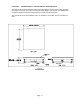
1-1 Standard Style......................................................................................................................... 1-1
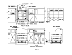
1-2 Detail View - Standard Style ................................................................................................... 1-2
1-3 Low Profile Style ..................................................................................................................... 1-3
1-4 Full Well Style ......................................................................................................................... 1-4
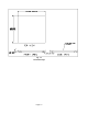
2-1 Bottom Of Scale (Shipping Screw) ......................................................................................... 2-1
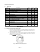
2-2 Corner Detail ........................................................................................................................... 2-2
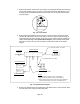
2-3 System Block Diagram............................................................................................................ 2-2
2-4 Bottom Of Scale (Shipping Screw) ......................................................................................... 2-3
2-5 Corner Detail ........................................................................................................................... 2-3
2-6 Corner Detail ........................................................................................................................... 2-4
2-7 Display Cut Out Detail............................................................................................................. 2-5
2-8 Display Cable Detail................................................................................................................ 2-6
2-9 Keypad Cut Out Detail ............................................................................................................ 2-7
2-10 Keypad Cable Detail ............................................................................................................... 2-8
2-11 Color Codes for Shielded Load Cell Cable ............................................................................. 2-9
2-12 Pin Assignments for the Load Cell Port .................................................................................. 2-9
2-13 Pin Assignments for the Summing Card................................................................................. 2-9
2-14 Pin Assignments for the DSUB9 serial port connector ........................................................... 2-10
3-1 Setup Menu Key Assignments................................................................................................ 3-2
3-2 Setup Menu Chart ................................................................................................................... 3-2
3-3 User Menu Chart..................................................................................................................... 3-4
5-1 User Menu Key Assignments.................................................................................................. 5-2
6-1 Setup Menu Key Assignments................................................................................................ 6-1
7-1 600E LED Display Detail......................................................................................................... 7-1
7-2 Function Keys Layout ............................................................................................................. 7-2
B-1 Cable Diagram for Indicator to IBM PC .................................................................................. B-1
B-2 Consolidated Controls Demand Mode.................................................................................... B-1
B-3 Print Ticket .............................................................................................................................. B-2
B-4 Cable Diagram for Indicator to Printer .................................................................................... B-2
B-5 Consolidated Controls Continuous Mode ............................................................................... B-3
LIST OF TABLES
2-1 Parts List ................................................................................................................................. 2-1
6-1 Calibration Value Table........................................................................................................... 6-2
7-1 600E Annunciator Definitions.................................................................................................. 7-2
C-1 Minimum Recommended Span Gain Table............................................................................ C-2